Yes, I have used Tesa 51036 fabric tape extensively on the White Bug's engine harness.
viewtopic.php?f=3&t=6195&start=140#p159404
Oftentimes, I just wrapped it around the ends of split loom, to prevent the loom from slipping off the bundle radially. I also used the tape to hold the harness together prior to split loom installation (imagine like a broccoli elastic, with a spacing every 3-12 inches).
On my project, you can see I generally made half-pipe brackets to support the harness (covered with split loom):
http://www.fiero.com/forum/Forum2/HTML/142133-2.html#p60
After sandblasting and painting, I used two strips of Tesa 51036 to secure the harness to the half-pipe.
I don't like wrapping very long continuous spirals, because if you ever have to service the harness, it's far more of a PITA to have to unwrap everything. For some short runs I used the Tesa 51036 exclusively without split loom.
The factory at work actually keeps Tesa 51036 in stock (among other tapes). The wire harnesses they build are mostly for buses. I decided to try what the factory used on my personal car, and I am satisfied with it.
As I understand it, 51026 is an older model that has been superseded by 51036. However, being a good supplier, Tesa didn't pull the rug from underneath existing happy customers. Don't piss off current customers by changing things when they're perfectly happy with their tested and reliable solution.
********************************************************************************
Use nylon split loom, not polyethylene. PE won't handle engine bay heat. Nylon typically has a white stripe running down the side. To avoid buying entire new spools for short segments, I raided cars at the u-pull, and then thoroughly washed (hot water + oven cleaner) the split loom. If the split loom was on an engine, you'll probably be OK.
********************************************************************************
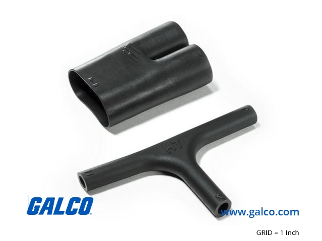
I didn't know about those heatshrink connectors. Looks like they're intended to be used with flexible PVC wire sleeves. PVC wire sleeves are more "Japanese-style". I guess if the heatshrink connectors come in an adhesive-lined version, I would suggest that so they remain stuck to the PVC wire sleeves.
The harness-building method I am familiar with is to build a full-scale pegboard, and then lay the wires onto the pegboard. Pegs determine the locations of various tap-offs. Once the wires are laid out, the harness is then wrapped/covered at the next station.
Having to slide all the connectors and tubes does not seem compatible with the pegboard paradigm of harness-building.
********************************************************************************
For your harness, you should know how to do wire splices; I'll post later on that subject.
I guess I should also say a word or two on SAE J1128 wire, and anything else that comes to mind.
********************************************************************************
Maybe you can split off the "wiring best practices" posts into its own thread, and clean up this thread and keep this one the PVC tape comparison?