so i was doing some research reading all that will has said about the front suspension of the fiero.
in one of the threads he suggests to lower the whole cradle a certain amount to straighten/parallel the lower control arms to the ground.
what if you were to do this and ALSO use the lowering ball joints? would that put you back to stock ride height?
and i was also thinking, people put tubular lower control arms into mustang II front suspensions without a strut rod by welding in pivots to the lower part of the crossmember. why wouldnt we be able to do that?
this is what im sorta referring to
http://www.fulltiltstreetrods.com/ford_into_ford.htm
thoughts?
i believe the upper arm is angled down in stock form, correct? is there any way to correct that with relocating the upper arm mount?
ive been reading on suspension design and i want to improve what i have as i build my bare framed car from the ground up.
front suspension questions, possible idea
Moderator: Series8217
-
Flyguyeddy
- Posts: 4
- Joined: Sun Nov 30, 2008 11:28 am
front suspension questions, possible idea
Brandon Edmonds
1998 Contour SVT (new sexiness)
1996 Taurus SHO (traded)
1984 Fiero (bare rust free frame, to be the basis for my car)
1991 Honda VFR750F interceptor (V4 sex)
1998 Contour SVT (new sexiness)
1996 Taurus SHO (traded)
1984 Fiero (bare rust free frame, to be the basis for my car)
1991 Honda VFR750F interceptor (V4 sex)
-
The Dark Side of Will
- Peer Mediator
- Posts: 15635
- Joined: Wed Nov 24, 2004 11:13 pm
- Location: In the darkness, where fear and knowing are one
- Contact:
What I was talking about was reducing the pro-dive in the front suspension by spacing the crossmember (and LCA forward inner pivot) away from the chassis, but keeping the LCA rear inner pivot in the stock location.
The relationship of the UCA to LCA would not change. Doing this with a method of lowering is exactly what I'm planning. I have a set of 2" aluminum lowering knuckles from Street Dreams. Two inches of lowering + 1 inch of raising = 1" lower and a good rake/stance.
You want the forward and rear inner pivots for the LCA spaced widely apart to react braking forces with minimal torque on the crossmember (it's not really that strong).
Hint: Most street rodders just want cool looking suspension to fit. They don't give a crap about real handling. Don't take your geometric advice from that crowd.
-
Flyguyeddy
- Posts: 4
- Joined: Sun Nov 30, 2008 11:28 am
ah got ya. so the relocating the rear pivot OR lowering the crossmember is pretty much the best way?
if i was to make my own coolant tubes, would i be able to relocate the rear pivot? (i say that because it seems to me thats the problem with moving them)
im glad you answered this, question i was hoping u would answer first at least.
if i was to make my own coolant tubes, would i be able to relocate the rear pivot? (i say that because it seems to me thats the problem with moving them)
im glad you answered this, question i was hoping u would answer first at least.
Brandon Edmonds
1998 Contour SVT (new sexiness)
1996 Taurus SHO (traded)
1984 Fiero (bare rust free frame, to be the basis for my car)
1991 Honda VFR750F interceptor (V4 sex)
1998 Contour SVT (new sexiness)
1996 Taurus SHO (traded)
1984 Fiero (bare rust free frame, to be the basis for my car)
1991 Honda VFR750F interceptor (V4 sex)
-
p8ntman442
- cant get enough of this site!
- Posts: 3289
- Joined: Wed Mar 30, 2005 2:37 pm
I dont follow this. Wont the torque increase as you increase the distance from the crossmember? Or will it be dissapated by the flexing of more steel the farther you go out?The Dark Side of Will wrote:
You want the forward and rear inner pivots for the LCA spaced widely apart to react braking forces with minimal torque on the crossmember (it's not really that strong).
Can you imagine autox'ing with that mustange setup? I hope they gusset in the cross member it looks preety weak and prone to fatigue in that picture.
"I wanna make a porno starring us. Well, not just us, also these two foreign bitches."
-
Series8217

- 1988 Fiero Track Car
- Posts: 5984
- Joined: Thu Jun 02, 2005 9:47 pm
- Location: Los Angeles, CA
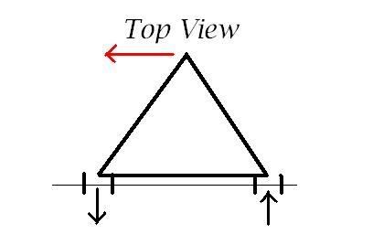
Will is saying to space the inner pivots out on the crossmember. I.E. the "A" of the A-arm is wider.
If you try pushing the top of a narrow "A" to the left or right, it's easy to bend the legs (and their attachment point; i.e. the crossmember).
If the A is very wide, it will be harder to bend because you are pushing along an axis closer to the axis of the leg, rather than perpendicular to it.
It's like tipping over a post vs. pushing over a pyramid. The braking force acts in the same direction, trying to push the top point of the A forward.
-
The Dark Side of Will
- Peer Mediator
- Posts: 15635
- Joined: Wed Nov 24, 2004 11:13 pm
- Location: In the darkness, where fear and knowing are one
- Contact:
What Steven said. As far as the brake torque and spread of the arm, I was speaking in plan view rather than side view.
I was thinking that as well. Most Street Rod components are built for packaging and looks with performance a distant third (or fourth or fifth).p8ntman442 wrote: Can you imagine autox'ing with that mustange setup? I hope they gusset in the cross member it looks preety weak and prone to fatigue in that picture.
-
The Dark Side of Will
- Peer Mediator
- Posts: 15635
- Joined: Wed Nov 24, 2004 11:13 pm
- Location: In the darkness, where fear and knowing are one
- Contact:
My take is that it would be easier to space the crossmember, but you may be able to raise the rear pivot without much fabrication.Flyguyeddy wrote:ah got ya. so the relocating the rear pivot OR lowering the crossmember is pretty much the best way?
if i was to make my own coolant tubes, would i be able to relocate the rear pivot? (i say that because it seems to me thats the problem with moving them)
im glad you answered this, question i was hoping u would answer first at least.
Think about the differences in geometry, though.
-
p8ntman442
- cant get enough of this site!
- Posts: 3289
- Joined: Wed Mar 30, 2005 2:37 pm
Series8217 wrote:Will is saying to space the inner pivots out on the crossmember. I.E. the "A" of the A-arm is wider.
If you try pushing the top of a narrow "A" to the left or right, it's easy to bend the legs (and their attachment point; i.e. the crossmember).
If the A is very wide, it will be harder to bend because you are pushing along an axis closer to the axis of the leg, rather than perpendicular to it.
It's like tipping over a post vs. pushing over a pyramid. The braking force acts in the same direction, trying to push the top point of the A forward.
No. If the height of the A remains the same, but the base gets wider, a greater force is applied to the mounting point.
The pyramid analagy is bogus because center of gravity is the major factor in that case.
Draw a free body diagram and you will see I'm right.
How do you figure the forces are less in plan view? Thats the way I was looking at it.[/quote]will wrote:What steve said
"I wanna make a porno starring us. Well, not just us, also these two foreign bitches."
-
Series8217
- 1988 Fiero Track Car
- Posts: 5984
- Joined: Thu Jun 02, 2005 9:47 pm
- Location: Los Angeles, CA
Your drawing is incomplete. Draw it again and consider the torque about the inner pivot bushing.
With a nearly infinite angle between the arms (as widely spaced as possible), you get the 1x braking force at the inner pivot point.
With a zero angle between the arms, you get a stupid amount of torque at the inner pivot point -- the length of the control arm divided by the distance between the bushings flanges. For a 1" wide clevis holding the inner pivot for the arm, and a 10" long control arm, that's 10x braking force on the clevis flanges!
-
p8ntman442
- cant get enough of this site!
- Posts: 3289
- Joined: Wed Mar 30, 2005 2:37 pm
Re: front suspension questions, possible idea
And God, becoming increasingly angry at his wayward subject, did posteth the Holy FBD, and it was good. His subjects did then look upon the FBD, and firstly noticed the uppermost words. Then, being ashamed, they cast their eyes downwards, and did notice the Most Holy Braking Force, acting in the rearward direction; this force being allowed by his Most High to be resolved into two seperate forces acting on the chassis in the directions shown (yea there's shear also...use your imagination, I forgot to put it in before I...err...God uploaded it)
Indy DOHC Turbo SD4.....someday.
Oh, and f*ck the envelope. (RFT Insurgent)
Oh, and f*ck the envelope. (RFT Insurgent)
-
p8ntman442
- cant get enough of this site!
- Posts: 3289
- Joined: Wed Mar 30, 2005 2:37 pm
Re: front suspension questions, possible idea
sumforces=0
you have the braking force and the two reactions. So unless you locate the tire farther out from the subframe, the braking force remains constant.
Agreed?
with the symetrical setup each reaction takes half the force. Your FBD should be labled f/2 at each reaction.
Agreed?
Ok Move your mounting points anyfuckinwhere you want but keep the a-arm symetrical and keep the tire in the same place.
You still have the same braking force, and you still have two reactions each f/2.
where am I going wrong?
"I wanna make a porno starring us. Well, not just us, also these two foreign bitches."
Re: front suspension questions, possible idea
It's a sin of omission. YES, SUM(F_x, F_y) = 0 , BUT that's not all of it. SUM(M)=0. The braking force is resolved not only by shear forces acting parallel to it(which aren't in my drawing but are just as important, well, more important usually), but also by a couple MOMENT reacted by the forces shown. Think about how you would solve this statics problem. The shear force reactions at the bottom points (lets call them B & C) are indetertiminate, but not particularly important in this discussion. However, to determine the magnitude of the reactions normal to the braking force F_A at B & C, you would take the moment around either point. These forces ARE equal to each other in magnitude but NOT equal to half the braking force. If it's 8" from the BC axis out to the braking force, and B & C are 12" apart, then SUM(M_B) = 8(F_A) - 12(F_C) = 0. So in this case, F_C = .667 F_A. Then the forces are summed in the other direction and F_B is found to be the same magnitude.
-
p8ntman442
- cant get enough of this site!
- Posts: 3289
- Joined: Wed Mar 30, 2005 2:37 pm
Re: front suspension questions, possible idea
yup. I had to draw it, but for being my first statics problem since I boxed up my books 3 years ago, I feel ashamed.
Anyways, I conceed that with a 12" base between mounting points and an 8" wheel to frame distance, you get 2/3 braking force acting on your pin connections.
At 24" you get 1/3 your braking force at each connection.
Now the real engineering question is (since the last ones were kind of ridiculous).
is a reduction in wheel distanc from frame, or a greater width in mounting points a better gain.
"I wanna make a porno starring us. Well, not just us, also these two foreign bitches."
-
The Dark Side of Will
- Peer Mediator
- Posts: 15635
- Joined: Wed Nov 24, 2004 11:13 pm
- Location: In the darkness, where fear and knowing are one
- Contact:
Re: front suspension questions, possible idea
Since all engineering problems are a series of compromises, it should be noted that the length of the control arm is dictated by factors other than the ability to withstand braking force.
-
Series8217
- 1988 Fiero Track Car
- Posts: 5984
- Joined: Thu Jun 02, 2005 9:47 pm
- Location: Los Angeles, CA
Re: front suspension questions, possible idea
For example, longer control arms provide for less change in wheel alignment thorough the suspension travel compared to shorter arms.