Durbal has a product the US website calls DDS (Durbal dirt shields?). The email tech support says they're called DDG in German and on page 122 of the catalog.
http://www.durbal.com/durbal-product_catalog-2011.pdf
They look exactly like the Pro-Works sealing washers... I wonder if Pro-Works gets their stuff from Durbal. Only so many ways to skin a cat, though.
The Mule rides again (sort of) - pics.
Moderators: The Dark Side of Will, Series8217
-
The Dark Side of Will
- Peer Mediator
- Posts: 15630
- Joined: Wed Nov 24, 2004 11:13 pm
- Location: In the darkness, where fear and knowing are one
- Contact:
-
The Dark Side of Will
- Peer Mediator
- Posts: 15630
- Joined: Wed Nov 24, 2004 11:13 pm
- Location: In the darkness, where fear and knowing are one
- Contact:
Re: The Mule rides again (sort of) - pics.
I *think* that the bushing version of this is: 527733R000 with a Hyundai list price of $18.77... that's a lot better than a $60 ball joint if I just want to get dimensions.The Dark Side of Will wrote: Edit again: Call out 38002, which is very different than the 55130 part number; it fits 33 variants and 7 models from 2006 to 2013.
http://www.jimellishyundaiparts.com/pro ... 4D000.html
However, there are a bunch of bushings that come up on Amazon when I search for the ball joint part number.
The part number for the through bolt is 527122G000, but the Hyundai catalog doesn't give the diameter/pitch info... Grrr...
-
The Dark Side of Will
- Peer Mediator
- Posts: 15630
- Joined: Wed Nov 24, 2004 11:13 pm
- Location: In the darkness, where fear and knowing are one
- Contact:
Re: The Mule rides again (sort of) - pics.
Juggs has a beading tool that (apparently) doesn't knurl the inside surface of the tubing...
http://www.jegs.com/i/JEGS-Performance- ... ProductId=
http://www.jegs.com/i/JEGS-Performance- ... ProductId=
The Dark Side of Will wrote:Just got off the phone with Brian at Graham Tool.
The hand-held tools have a different die set for each tubing size. They cater to the aviation maintenance professional (AMP) market. That use case is driven by mil-specs and ANSI standards which specify the surface finish for the inside of the tube where it has been beaded. That and the occasional need to bead tubes while still installed to the aircraft drives the tool to be similar to a hand-held tubing cutter.
So to use the large hand-held tool for what I need, I'd have to get the $150 tool with 1.25" die set installed, AND order the 1.5" die set for an additional $70-$80.
They are shortly (next week) coming out with a vice-mounted tool for the automotive market that is operated by a hand-crank. This tool uses one die set to bead from 1" to 6" diameter tube. It is operated by a crank. Because the inner die has to have "traction" to turn the tube, it is slightly knurled. This marks the inside of the tube and makes the resultant bead not acceptable for aviation use. It's fine for automotive use, however.
That tool will be $225 + free standard shipping... so for the same price as the hand-held tool, I get the capability to do a vastly greater number of sizes.
Their photo montage describing use of their tool also shows use of an ID deburring tool. I've used these tools before, but I don't think I've ever seen them for sale.
Here are a couple of sites which sell their own varieties.
http://www.royalprod.com/product.cfm?catID=7
http://www.noga.com/
-
ericjon262
- Posts: 2833
- Joined: Mon May 24, 2010 5:34 pm
- Location: Aiken, SC
Re: The Mule rides again (sort of) - pics.
that's a pretty slick tool, I'll add that to my list....
"I am not what you so glibly call to be a civilized man. I have broken with society for reasons which I alone am able to appreciate. I am therefore not subject to it's stupid laws, and I ask you to never allude to them in my presence again."
-
The Dark Side of Will
- Peer Mediator
- Posts: 15630
- Joined: Wed Nov 24, 2004 11:13 pm
- Location: In the darkness, where fear and knowing are one
- Contact:
Re: The Mule rides again (sort of) - pics.
So I've not had very good luck finding the product I *really* want for my spherical bearing conversion.
I had envisioned using a sealed spherical bearing or through bolt ball joint or pillow ball or whatever people call them in a housing and with a pair of spacers which would allow the combo to be used in the '84-'87 front and rear control arms, as well as the '88 front control arms.
I had also thought about using small needle bearings in the '84-'87 rear and '88 front, because those pivots were co-axial and didn't need any angularity. I decided to pursue using spherical bearings everywhere because it wasn't a good application for needles and because I wanted the elegant design bragging rights of being able to use the same parts for everything.
So I've solved the problem of using the same parts for everything. I have a design that will work. However, I don't have a spherical bearing that will work.
In other news, I had been thinking about hard pivots for BMW semi-trailing arms. These bushings are very small in diameter, which is good for a rubber bushing. However, it's not so good for using spherical bearings or ball joint.
There are "plain linear bearings" which could do the job just fine AS LONG AS the control arm pivots are coaxial.
Per BMW, the OD of the E30 trailing arm bushings is 30mm, and those bushings mount on 12mm bolts... so whatever I can use in the E30, I can also use in the Fiero applications.
http://www.realoem.com/bmw/showparts.do ... g=33&fg=30
So over the weekend I realized that I just need to use the plain linear bearings in the early rear and 88 front and find the right spherical bearing for the early front later.
So on to McMaster:
Common sizes for "Fixed alignment linear sleeve bearings" have 1 1/8 OD and run on 5/8" shafts.

Of the available liner and shell materials, PTFE liner with fiberglass shell and ceramic liner with aluminum shell both have load capacities of 4691 lbs in the size that interests me. The PTFE liner has a max PV of 30,000 and the ceramic liner has a max PV of 40,000 but "requires a thin film of lubrication". I'm not sure exactly what that means from the implementation perspective.
At 1 1/2" long, they have a lot more bearing area than a spherical bearing.
Those part numbers are 6673k14 and 8356K13
Both types require 8-16 RA surface finish on the shaft, so I'll have to use precision ground rod and drill it--NOT fun since precision ground rod is typically hardened in the neighborhood of Rockwell C60--for the 12mm through bolts.
McMaster does list "tubular shafts" with precision ground exterior at 9 RA and Rockwell C58, but the smallest OD they show is 3/4". I guess I could call and ask if they can get 5/8 OD.
Also, 12mm clearance (31/64") and 5/8" OD leave a 0.070" wall thickness. This is pretty thin to be clamped to the mounting ears for the bushings with 12mm bolts pulled hard (80 ftlbs?). I'd like to spread that load out a bit.
Hmm... 31/64 drill bushings with heads have 3/4" OD, so they're too large.
However, the 8492A243 drill bushing has 5/8" diameter, 3/4" depth with a 7/16" hole that could be drilled (with carbide!) out to 31/64. The length tolerance is +/-.010, so I'll have to look up what the length tolerance on the linear bearings is...
I had envisioned using a sealed spherical bearing or through bolt ball joint or pillow ball or whatever people call them in a housing and with a pair of spacers which would allow the combo to be used in the '84-'87 front and rear control arms, as well as the '88 front control arms.
I had also thought about using small needle bearings in the '84-'87 rear and '88 front, because those pivots were co-axial and didn't need any angularity. I decided to pursue using spherical bearings everywhere because it wasn't a good application for needles and because I wanted the elegant design bragging rights of being able to use the same parts for everything.
So I've solved the problem of using the same parts for everything. I have a design that will work. However, I don't have a spherical bearing that will work.
In other news, I had been thinking about hard pivots for BMW semi-trailing arms. These bushings are very small in diameter, which is good for a rubber bushing. However, it's not so good for using spherical bearings or ball joint.
There are "plain linear bearings" which could do the job just fine AS LONG AS the control arm pivots are coaxial.
Per BMW, the OD of the E30 trailing arm bushings is 30mm, and those bushings mount on 12mm bolts... so whatever I can use in the E30, I can also use in the Fiero applications.
http://www.realoem.com/bmw/showparts.do ... g=33&fg=30
So over the weekend I realized that I just need to use the plain linear bearings in the early rear and 88 front and find the right spherical bearing for the early front later.
So on to McMaster:
Common sizes for "Fixed alignment linear sleeve bearings" have 1 1/8 OD and run on 5/8" shafts.
Of the available liner and shell materials, PTFE liner with fiberglass shell and ceramic liner with aluminum shell both have load capacities of 4691 lbs in the size that interests me. The PTFE liner has a max PV of 30,000 and the ceramic liner has a max PV of 40,000 but "requires a thin film of lubrication". I'm not sure exactly what that means from the implementation perspective.
At 1 1/2" long, they have a lot more bearing area than a spherical bearing.
Those part numbers are 6673k14 and 8356K13
Both types require 8-16 RA surface finish on the shaft, so I'll have to use precision ground rod and drill it--NOT fun since precision ground rod is typically hardened in the neighborhood of Rockwell C60--for the 12mm through bolts.
McMaster does list "tubular shafts" with precision ground exterior at 9 RA and Rockwell C58, but the smallest OD they show is 3/4". I guess I could call and ask if they can get 5/8 OD.
Also, 12mm clearance (31/64") and 5/8" OD leave a 0.070" wall thickness. This is pretty thin to be clamped to the mounting ears for the bushings with 12mm bolts pulled hard (80 ftlbs?). I'd like to spread that load out a bit.
Hmm... 31/64 drill bushings with heads have 3/4" OD, so they're too large.
However, the 8492A243 drill bushing has 5/8" diameter, 3/4" depth with a 7/16" hole that could be drilled (with carbide!) out to 31/64. The length tolerance is +/-.010, so I'll have to look up what the length tolerance on the linear bearings is...
-
The Dark Side of Will
- Peer Mediator
- Posts: 15630
- Joined: Wed Nov 24, 2004 11:13 pm
- Location: In the darkness, where fear and knowing are one
- Contact:
Re: The Mule rides again (sort of) - pics.
3.61 output shaft on left, 3.94 on right:
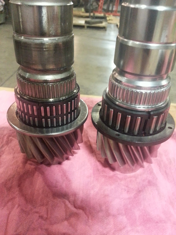
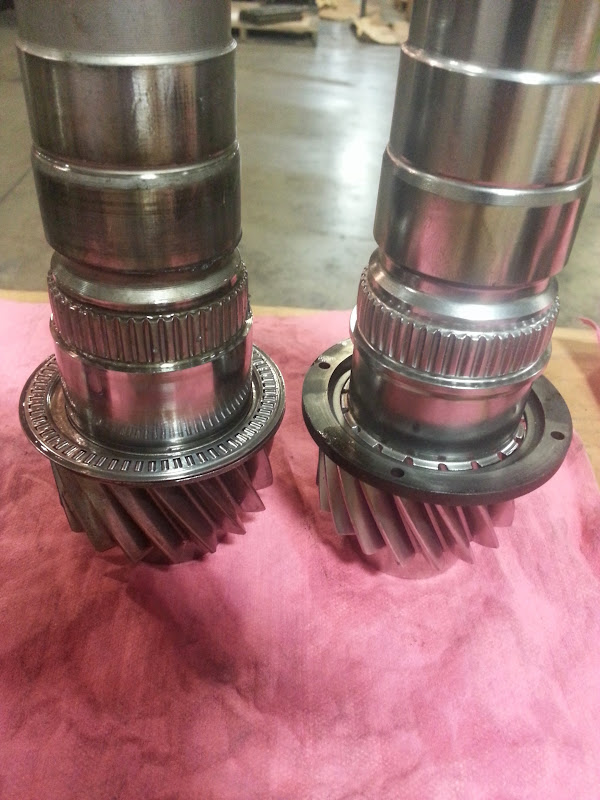


Got the 2.50/1.85 output cluster apart over the weekend and installed the modded first gear, modded 1-2 synchro, stock 2nd gear bearing race and modded 2nd gear to the 3.94 output shaft I'd had treated a while back.
The $25 deep fryer I've used to heat the parts malfunctioned, so my dad and I didn't get the 1.02 3-4 cluster installed on the 3.94 shaft, but we're this || close.
I meant to get the "money shot" of the welded 1st and 2nd gears next to the 3.94 output... and I had everything laid out, but then got distracted and never actually took the photo.
-
Shaun41178(2)

- Posts: 8375
- Joined: Fri Nov 19, 2004 7:12 pm
- Location: Ben Phelps is an alleged scammer
Re: The Mule rides again (sort of) - pics.
I thought that custom 1-2 was broken? I thought the 3800 guy broke it?
So you are doing 2.50, 1.85, 1.38, 1.02, .72?
Or is 5th going to be the higher .80? Thats a tight ratio trans, Should rip.
Speed per gear at 6k rpm?
So you are doing 2.50, 1.85, 1.38, 1.02, .72?
Or is 5th going to be the higher .80? Thats a tight ratio trans, Should rip.
Speed per gear at 6k rpm?
-
The Dark Side of Will
- Peer Mediator
- Posts: 15630
- Joined: Wed Nov 24, 2004 11:13 pm
- Location: In the darkness, where fear and knowing are one
- Contact:
Re: The Mule rides again (sort of) - pics.
I'll be keeping the 0.72. The 0.81 would be a great performer in 5th, but I can't quite handle 3300 RPM at 80. As it is, the 3.94 will boot me from 2700 to about 2900. When I build an F40, I'll go for the 0.81 fifth and 0.62 sixth with the 3.91 final. That will give me a rippin' gearset up to 5th, but with a top gear about the same as that of the 3.35 Isuzu or Econo Muncie.
The input shaft was poorly modified and broke. The gears are fine. I have a better idea for how to install the input cluster than was used previously, and will be getting that done soon.
I'll be turning 7000 to 7500.
Speeds at 7k:
1st: 54 mph
2nd: 73
3rd: 98
4th: 132
5th: 188
With 245/50-16 tires (25.6 inches tall)
The change from 3.5*3.61 to 2.5*3.94 results in a loss of about 28% of axle torque in first gear. I hope that helps me not break CV joints in the future. I'll get some of that acceleration back as I mod the engine, but I think I'll have a hoot being able to drop it in first at 30 and be right at the beginning of the powerband at 4000 RPM.
-
The Dark Side of Will
- Peer Mediator
- Posts: 15630
- Joined: Wed Nov 24, 2004 11:13 pm
- Location: In the darkness, where fear and knowing are one
- Contact:
Re: The Mule rides again (sort of) - pics.
This plain linear bearing uses a 3/4" shaft and has a 1.125" OD... that would be perfect. if used with other means of dealing with the thrust load.
https://sdp-si.com/eStore/Catalog/PartN ... -075124162
However, I may want to use a pair of flanged plain linear bearings to deal with longitudinal loads... but the flange OD's on those jump from 1" to 1.25" and skip 1.125 and 1.187. Oops.
I might be able to use PSF1216-08 from here: http://www.pbclinear.com/(PSF)-Simplici ... ve-Bearing
It fits a 3/4" shaft, has a 1" sleeve OD, 1.25" flange OD and an overal length of 1". Using two sleeve to sleeve with the flanges outward would put the flanges far enough apart that location of the resulting thin wall will be mostly outside the high load part of the shell. I'll have to sketch it out, but I think I can be comfortable with that. Another similar product: http://www.qbcbearings.com/BuyRFQ/Linea ... F_SL_I.htm
Also: BSNFLN-12FTH16 here: http://www.qbcbearings.com/BuyRFQ/Sleev ... F_SL_I.htm#
Is a similar product, but split... which basically just means it's more flexible with housing diameter. It has 3/4" shaft size, 7/8" sleeve OD, and 1.125 flange OD with 1.000 overall length.
ALSO... ran across mention of ceramic coated aluminum as a shaft material for linear bearings. I was reminded of the ceramic aluminum piston pins that Hank The Crank used to make (and a set of which I wanted for the Northstar). I wonder if that's a DIY route...
-
FieroWanaBe1
- Posts: 427
- Joined: Sun Mar 11, 2007 11:26 pm
Re: The Mule rides again (sort of) - pics.
So If i understand this right you want to use a bush, with a through bolt for clamp load?The Dark Side of Will wrote:
Both types require 8-16 RA surface finish on the shaft, so I'll have to use precision ground rod and drill it--NOT fun since precision ground rod is typically hardened in the neighborhood of Rockwell C60--for the 12mm through bolts.
McMaster does list "tubular shafts" with precision ground exterior at 9 RA and Rockwell C58, but the smallest OD they show is 3/4". I guess I could call and ask if they can get 5/8 OD.
Also, 12mm clearance (31/64") and 5/8" OD leave a 0.070" wall thickness. This is pretty thin to be clamped to the mounting ears for the bushings with 12mm bolts pulled hard (80 ftlbs?). I'd like to spread that load out a bit.
Hmm... 31/64 drill bushings with heads have 3/4" OD, so they're too large.
However, the 8492A243 drill bushing has 5/8" diameter, 3/4" depth with a 7/16" hole that could be drilled (with carbide!) out to 31/64. The length tolerance is +/-.010, so I'll have to look up what the length tolerance on the linear bearings is...
Why not use shoulder bolts?
such as? 91259A802...
I would say the nature of suspension loading may allow the surface finish to deviate more. Its more impact heavy loading and the race will be beat up and face plastic deformation as a primary failure mechanism more than its erode away by a rough surface (and it will never have much more that 30 degrees of total articulation, localizing wear to a specific area.)
car.
-
The Dark Side of Will
- Peer Mediator
- Posts: 15630
- Joined: Wed Nov 24, 2004 11:13 pm
- Location: In the darkness, where fear and knowing are one
- Contact:
Re: The Mule rides again (sort of) - pics.
I could use shoulder bolts. It might be hit or miss whether I could find bolts EXACTLY the right length. I hadn't looked into it yet, but that's an interesting idea.FieroWanaBe1 wrote:So If i understand this right you want to use a bush, with a through bolt for clamp load?The Dark Side of Will wrote:
Both types require 8-16 RA surface finish on the shaft, so I'll have to use precision ground rod and drill it--NOT fun since precision ground rod is typically hardened in the neighborhood of Rockwell C60--for the 12mm through bolts.
McMaster does list "tubular shafts" with precision ground exterior at 9 RA and Rockwell C58, but the smallest OD they show is 3/4". I guess I could call and ask if they can get 5/8 OD.
Also, 12mm clearance (31/64") and 5/8" OD leave a 0.070" wall thickness. This is pretty thin to be clamped to the mounting ears for the bushings with 12mm bolts pulled hard (80 ftlbs?). I'd like to spread that load out a bit.
Hmm... 31/64 drill bushings with heads have 3/4" OD, so they're too large.
However, the 8492A243 drill bushing has 5/8" diameter, 3/4" depth with a 7/16" hole that could be drilled (with carbide!) out to 31/64. The length tolerance is +/-.010, so I'll have to look up what the length tolerance on the linear bearings is...
Why not use shoulder bolts?
such as? 91259A802...
I would say the nature of suspension loading may allow the surface finish to deviate more. Its more impact heavy loading and the race will be beat up and face plastic deformation as a primary failure mechanism more than its erode away by a rough surface (and it will never have much more that 30 degrees of total articulation, localizing wear to a specific area.)
I was thinking that I would have the hard surface linear bearings for lateral loads and hard surface thrust washers for the axial load, or a pair of flanged linear bearings to take care of both types of loading.
In thinking about it a little more... I could take a page out of Gordon Murray's book
When I was making the UHMW bushings in the car now, dealing with end play was annoying. Selecting the right end play (.005? .010? -.005?) and then getting both UHMW *AND* steel parts made precisely enough to have only that much end play when I torqued up the bolts on the equipment I had available was full of unknowns. Because of the length tolerances of the plain linear bearings, it was looking like this effort would be similarly afflicted. That's why I started to look at flanged units, in order to keep the tolerances tight on the length stack-up. Sure I could make the sleeve to match the bearing I got in this order, but when/if that one wore out, where will its replacement be in the tolerance range? I could allow for the entire tolerance range, but at that point I'm getting up to .015 to .020 end play... which is probably completely inconsequential and utterly imperceptible but still bugged me.
I just realized that with the plain UNflanged linear bearings, I could just cut (order?) rubber cookies to go at each end of the bearing. I could clamp them at a very slight interference and the resulting drag wouldn't be a big deal compared to suspension forces and the tolerances should be fairly wide open.
So that means my assembly would be VERY stiff radially, but comparatively cushy axially... which is a lot like Gordon Murray's (subframe? control arm?) bushings for the McLaren F1!
Also, with the linear bearing for a 3/4" shaft noted above, I can use McMaster's 3/4" precision ground HOLLOW rod and make drilling the sleeves for bolts MUCH easier... but I'll also investigate shoulder bolts. One thing I don't like about shoulder bolts is that I'd have to drill at least one of the bolt holes in the mounting ears out to 3/4".
EDIT: And actually there's no reason I can't use rubber cushions with the flanged linear bearings, except that the cushions would get pretty thin.
-
The Dark Side of Will
- Peer Mediator
- Posts: 15630
- Joined: Wed Nov 24, 2004 11:13 pm
- Location: In the darkness, where fear and knowing are one
- Contact:
Re: The Mule rides again (sort of) - pics.
I just realized that with shoulder bolts, using the bolt shank as the bearing surface (I @$$ume that what you meant) you can't clamp the mounting ear that's under the bolt head. No-go.
-
The Dark Side of Will
- Peer Mediator
- Posts: 15630
- Joined: Wed Nov 24, 2004 11:13 pm
- Location: In the darkness, where fear and knowing are one
- Contact:
Re: The Mule rides again (sort of) - pics.
If I use two of the flanged plain linear bearings back to back with the flanges outward, I'd end up with one end of each configuration with .010 to .015 shim (or maybe just right on the mounting ear for simplicity). Interesting.
The two configurations are front and rear. They have the journals that mate to the control arms at different axial locations, which is what lets me design one shell to fit both applications. However, that means that I have different end spacer configurations--really just the same spacer and differing numbers of 0.100" thick ground washers at each end. For a bushing that's comparatively narrow, like a spherical bearing, the spacers are reasonable thicknesses. Even for a 1.625" long plain linear bearing, the spacer thicknesses are fine.
However, which the flange linear bearing pair + allowance for axial tolerance comes to 2.010 or maybe 2.020 depending on how unlucky I feel, I end up limited to .010 to .015 thick shims at one end or the other.
Idea: I could incorporate a spacer ring into the design which would be used behind one of the flanged bearings or the other depending on which end the assembly was being used for.
EDIT: Using Idea above... I come up with needing .060 rubber cushions at each end with a .100 spacer ring under the flange of one flanged bearing or the other.
McMaster doesn't have anything with the right ID, OD and thickness, BUT if I use a -018 o-ring on the shaft, a -020 o-ring outside the -018 and a -022 outside the -020, then I have the .070 thick rubber cushion with room to squeeze down to .060 and I get the ID and OD that I'm looking for! And it's using standard shelf parts that are available in a variety of materials for CHEAP CHEAP!
Ref for O-ring sizes: http://www.marcorubber.com/sizingchart.htm
Maybe now I can get this idea out of my head and regain control of my thinking...
-
FieroWanaBe1
- Posts: 427
- Joined: Sun Mar 11, 2007 11:26 pm
Re: The Mule rides again (sort of) - pics.
How much stiffness and how much deflection exist in the mounting ears for the control arms?
I feeling like your axial end play concerns may be a bit over-analytic, considering (especially at the front lowers) manufacturing tolerance of the sub-frames, sheet stiffness and the amount of clamp load. Most, if any, end play can be taken up by the required clamp load that it would take to secure the "shaft" and bolt.
And spec'ing shoulder bolts a little under the correct length is the approach I would use (or using washers to take up shaft length under the head), and rely on friction from the clamp load on the mounting ears to secure the bolt from rotation.
I feeling like your axial end play concerns may be a bit over-analytic, considering (especially at the front lowers) manufacturing tolerance of the sub-frames, sheet stiffness and the amount of clamp load. Most, if any, end play can be taken up by the required clamp load that it would take to secure the "shaft" and bolt.
This is how I would imagine the layout, with a ground washer on either end, if space allows, rubber washers, or bellvile washers for shock absorption in the axial direction.If I use two of the flanged plain linear bearings back to back with the flanges outward, I'd end up with one end of each configuration with .010 to .015 shim (or maybe just right on the mounting ear for simplicity). Interesting.
And spec'ing shoulder bolts a little under the correct length is the approach I would use (or using washers to take up shaft length under the head), and rely on friction from the clamp load on the mounting ears to secure the bolt from rotation.
car.
-
The Dark Side of Will
- Peer Mediator
- Posts: 15630
- Joined: Wed Nov 24, 2004 11:13 pm
- Location: In the darkness, where fear and knowing are one
- Contact:
Re: The Mule rides again (sort of) - pics.
Do you understand my concern about shoulder bolts?
I realized that for the single-axis pivots, I can use shaft seals on the spacers and conventional (or sealed) spherical bearings inside, completely protected by the shaft seals. This won't work on the '84-'87 front because of the eccentric motion of the pivot, but should be fine on the '88 front and '84-'87 rear.
My big concern about end play is impact loading and/or perceptible clunk.
-
FieroWanaBe1
- Posts: 427
- Joined: Sun Mar 11, 2007 11:26 pm
Re: The Mule rides again (sort of) - pics.
I don't think I do...The Dark Side of Will wrote:Do you understand my concern about shoulder bolts?
car.
-
The Dark Side of Will
- Peer Mediator
- Posts: 15630
- Joined: Wed Nov 24, 2004 11:13 pm
- Location: In the darkness, where fear and knowing are one
- Contact:
Re: The Mule rides again (sort of) - pics.
It has to do with what makes a bolted joint.
A bolted joint has something clamped with the tensile preload on the bolt that comes from tightening it. The strength of the joint comes from the FRICTION between the clamped parts and not from the surface hardness of the bolt or the edge of the hole.
To use a shoulder bolt as the bushing shaft, I'd have to drill out one mounting ear for the shoulder to pass through, then the threaded shank would go through the other mounting ear and have a nut tightened on it. That mounting ear would be clamped between the shoulder and the nut and would be a bolted joint. The OTHER mounting ear would NOT be a bolted joint... it would be a shaft passing through a hole. The edges of the mounting ear and shaft would be exposed to impact loading if it's less than an exact fit. The hole would get wallowed out and the shoulder would get worn, just like what happens to the '88 rear knuckles when the outer pivot bolt is loose.
-
FieroWanaBe1
- Posts: 427
- Joined: Sun Mar 11, 2007 11:26 pm
Re: The Mule rides again (sort of) - pics.
I see your concern now.
And the mounting tabs really aren't rigid enough to have any real load preventing that condition.
And the mounting tabs really aren't rigid enough to have any real load preventing that condition.
car.
-
Shaun41178(2)
- Posts: 8375
- Joined: Fri Nov 19, 2004 7:12 pm
- Location: Ben Phelps is an alleged scammer
Re: The Mule rides again (sort of) - pics.
update on transmission?
Also there is no way to use the 3.50/2.19 at all by replacing second? Can't be pressed on in any way? the mg1(turbo 2.0) supposedly has the 2.19 second but I am assuming it a rare trans whereas there are 3.77/2.19 is all over ebay so availability of that second gear is plenty and cheap.
Also there is no way to use the 3.50/2.19 at all by replacing second? Can't be pressed on in any way? the mg1(turbo 2.0) supposedly has the 2.19 second but I am assuming it a rare trans whereas there are 3.77/2.19 is all over ebay so availability of that second gear is plenty and cheap.
-
The Dark Side of Will
- Peer Mediator
- Posts: 15630
- Joined: Wed Nov 24, 2004 11:13 pm
- Location: In the darkness, where fear and knowing are one
- Contact:
Re: The Mule rides again (sort of) - pics.
The first and second gears are integral on the input shaft, so you need a 3.50/2.19 input shaft.
Check this out: http://60degreev6.com/forum/showthread. ... ing-by-RPO
and this: http://www.fiero.com/forum/Archives/Arch ... 36597.html
I think my 3.50/2.19 parts came from an '89 or '90 Beretta Q4 trans.
Ahh... here we go:
phpBB/viewtopic.php?p=87857#p87857
'90 Beretta
I haven't done anything else on the 2.50/1.85 trans yet. I need to bug my dad about gluing the retention magnet for the deep fryer's electrical plug back in so we can heat up the 3-4 cluster.
And I need to make a print of what I want done to the input shaft... I have a sketch, just need to formalize it a bit.