True. Now I will tell you that if this car was going to be a trailer queen, then the paint option would probably work and would probably last for a reasonably long time. But the customer has informed me that he plans to drive this car - a lot. Which I assume is going to be mostly during the summer months when the engine compartment is going to be the hottest.The Dark Side of Will wrote:Intake manifold repaints then become a maintenance cost associated with having a blingin' engine bay.
LS4 V8 DoD 4T65-E TAPShift swap underway (pics inside)
Moderators: The Dark Side of Will, Series8217
-
Sinister Fiero
- Posts: 665
- Joined: Tue Jun 07, 2005 12:10 pm
- Location: Waterloo, Indiana
- Contact:
i've never had a problem with heat when using the high temp engine paints on daily drivers.Sinister Fiero wrote:True. Now I will tell you that if this car was going to be a trailer queen, then the paint option would probably work and would probably last for a reasonably long time. But the customer has informed me that he plans to drive this car - a lot. Which I assume is going to be mostly during the summer months when the engine compartment is going to be the hottest.The Dark Side of Will wrote:Intake manifold repaints then become a maintenance cost associated with having a blingin' engine bay.
-
Sinister Fiero
- Posts: 665
- Joined: Tue Jun 07, 2005 12:10 pm
- Location: Waterloo, Indiana
- Contact:
The high-temp paint itself is fine -- when you paint metal. But it won't adhere to plastic; which is the purpose of adhesion promoter. The problem isn't with the paint; it's with the adhesion promoter that needs to be used with the plastic. There are currently no high-temperature adhesion promoters available; and that is the problem.Kohburn wrote:
i've never had a problem with heat when using the high temp engine paints on daily drivers.
-
The Dark Side of Will
- Peer Mediator
- Posts: 15635
- Joined: Wed Nov 24, 2004 11:13 pm
- Location: In the darkness, where fear and knowing are one
- Contact:
-
Sinister Fiero
- Posts: 665
- Joined: Tue Jun 07, 2005 12:10 pm
- Location: Waterloo, Indiana
- Contact:
Can't tell you specifics. I am not a body or paint man. The information I gave here is based on the many conversations I had with a friend of mine (Fred Bartemeyer who is well known to the Fiero community) who is very knowledgable in automotive painting, at least a lot more so than I. So if you want to debate this subject with him, be my guest. But we discussed this subject at length not too long ago as I had a customer inquiring about getting some 3800 plastic valve covers painted (and he wanted the paint to last).The Dark Side of Will wrote:The engine runs at 195ish, so the plastic manifold should be cooler, the exhaust hotter. What temp are adhesion promoters typically good for?
Just for giggles, I did a quick search of the net for product data sheets for these adh. promoters. Couldn't turn up any working environment temperature specs. What I did find was most of these adh. promoters appeared to have a "bake-on" temp spec of 120 deg F.
Now I do know you can have plastic chromed. I have seen this done to some stock LS1 plastic intakes. But I have no idea on cost or durability.
First a disclaimer, I'm no chemist, I'm a professional wood restorer and conservator and auto body painting is just my "hobby." So with that said I think that most of the plastic painting you see "aftermarket" in the engine bay that does hold up is being done with something a little more high tech. than your typical adhesion promoter. The prep. material is called a "tie" coat which can contain some fairly exotic chemistry (silane origomer as a modifier) that allows the paints that go over top of it to handle more heat. Here is one product that I am familiar with made by Transtar...
http://www.tat-co.com/product.asp?ID=198
This is still not to say that any heat stressed part is going to last as long as it's steel counterpart but I have personally seen plastic engine bay parts on higher end custom work that used these "tie" coats before painting and they have lasted many years. Personally I picked up some of this tie coat tech. from people in the conservation trades that are trying to arrest the deterioration of older collectable plastics. Strange how fields overlap, huh?
SUSPENSION AND BRAKE UPDATE
Ryan is the best! In between all of the MAJOR wiring work that he's doing to keep many of the original functionality of the DoD and DIC from the 2005 GXP Grand Prix to work with the Fiero, he's also been able to partner with me to do a rebuild of most of my suspension and brakes.
Here's how things looked before the work began...

As you can read in earlier posts, I had Ryan send me the control arms and spindles, which I media blasted, checked for any structural issues, and then powder coated them. I have the WCF performance springs and Koni shocks installed. Also new tire rods from The Fiero Store. I originally tried to go cheap and bought some from ebay, but they were crap...so ended up paying the extra bucks and got them at TFS. I haven't replaced the front sway bar yet, but will do so myself when I get the car back. I do have the rear sway bar from TFS, as well as all the poly bushings.


You can also see the 12" Corvette rotors from Rockcrawl's Brake Kit installed. Ryan is currently working on getting the 88' Fiero calipers installed such that it works with Rockcrawl's Kit. I originally hoped I could get my OEM wheels to fit these rotors, but no such luck. It would take alot of grinding away at the rims and that would just not make alot of sense. I wanted to keep the OEMs as Winter Tires or even drag strip rims...but no such luck. I will likely put these up for sale if there is any interest. You can see them in one of the pictures above.
Right now, I'm looking for wheels/tires that will make the most of my current setup. I have coil overs in the rear, so I'm going to go as wide as my pocket book will allow!
My preference is a staggered height setup, similar to the Corvette's by going 17 x 8.0 w/ @ 42mm offset and 225/40 tires in the front and 18 x 8.0 w/ 35mm offset and 265/35 tires in the rear. Its the rear that's been the hardest to find in affordable performance tires.
More to come....
Ryan is the best! In between all of the MAJOR wiring work that he's doing to keep many of the original functionality of the DoD and DIC from the 2005 GXP Grand Prix to work with the Fiero, he's also been able to partner with me to do a rebuild of most of my suspension and brakes.
Here's how things looked before the work began...
As you can read in earlier posts, I had Ryan send me the control arms and spindles, which I media blasted, checked for any structural issues, and then powder coated them. I have the WCF performance springs and Koni shocks installed. Also new tire rods from The Fiero Store. I originally tried to go cheap and bought some from ebay, but they were crap...so ended up paying the extra bucks and got them at TFS. I haven't replaced the front sway bar yet, but will do so myself when I get the car back. I do have the rear sway bar from TFS, as well as all the poly bushings.
You can also see the 12" Corvette rotors from Rockcrawl's Brake Kit installed. Ryan is currently working on getting the 88' Fiero calipers installed such that it works with Rockcrawl's Kit. I originally hoped I could get my OEM wheels to fit these rotors, but no such luck. It would take alot of grinding away at the rims and that would just not make alot of sense. I wanted to keep the OEMs as Winter Tires or even drag strip rims...but no such luck. I will likely put these up for sale if there is any interest. You can see them in one of the pictures above.
Right now, I'm looking for wheels/tires that will make the most of my current setup. I have coil overs in the rear, so I'm going to go as wide as my pocket book will allow!
My preference is a staggered height setup, similar to the Corvette's by going 17 x 8.0 w/ @ 42mm offset and 225/40 tires in the front and 18 x 8.0 w/ 35mm offset and 265/35 tires in the rear. Its the rear that's been the hardest to find in affordable performance tires.
More to come....
-
Sinister Fiero
- Posts: 665
- Joined: Tue Jun 07, 2005 12:10 pm
- Location: Waterloo, Indiana
- Contact:
Sorry for the lack of updates guys. There is a lot of new ground being broken in many areas of this swap which is requiring a lot of extra on-the-fly R&D to be done so the swap can progress. But it's getting there. Case in point: the wiring is quite litterally about 5x more involved with this swap compared to the typical 3800 swap after you factor in the BCM for this LS4 and what it wants to see and have control over in the car. And that's factor in what has been taking so long. I have to figure out what devices are essential (such as the brake pedal position sensor) and what devices and controls are not (headlight controls, etc). The ultimate goal with keeping the BCM is to implement the factory keyless entry and remote start that came on the Grand Prix it came out of and make it all work in the Fiero. The BCM is also needed because it tells the DIC when to turn on (there is no key-on voltage that goes to the DIC and other devices in these newer GM cars; the signal to turn them on comes across the class 2 data communications circuit).
As you can see in the above pictures posted by blkcofy, the front suspension is done and I have began working on the rear. The engine/trans/cradle went back into the car for the last time on Friday. I've already started hooking up the cooling system and wiring so it won't be long before this thing is ready to fire. One improtant thing I have yet to do is get back to the dealer to get the replacement ECM reflashed with the correct factory programming. I have to do this thru a third party and our schedules haven't sync'd up in the last 4 weeks but I'm still hopeful I can get this very important thing done before Christmas.
-ryan
-
p8ntman442
- cant get enough of this site!
- Posts: 3289
- Joined: Wed Mar 30, 2005 2:37 pm
-
Sinister Fiero
- Posts: 665
- Joined: Tue Jun 07, 2005 12:10 pm
- Location: Waterloo, Indiana
- Contact:
No mysterious reason, really. My original plans were to install front and rear sway bars using the purple Intrax bars. But after ordering it twice only to be told there was a 2-3 month delay...I quickly looked to another solution.
There was an very interesting HPP high end adjustable sway bar package I was going to purchase, that allowed various setups, but the rear bar would not work on my car as the way you have to connect it, it would intefere with Ryan's work on my exhaust. The only way to have both would have been to have Ryan cut into my trunk! Yikes!! So I dropped that route as well. Besides, it was almost twice the price as the Intrax.
Since then, I've invested in higher grade tie rods and ball joints, so I opted to install just the Rear Sway Bar from The Fiero Store (using poly mounts) and will replace the front at a later date. It seemed well within my own garage skill set to handle!
-
p8ntman442
- cant get enough of this site!
- Posts: 3289
- Joined: Wed Mar 30, 2005 2:37 pm
SUSPENSION UPDATE
In between the time Ryan has spent lecturing with his cohort professor AJxtcman on that "other" forum...on the finer aspects of GM ECM/TCM/BCM/PZM/DIM :scratch:. He's also managed to somehow continue to assemble my rear suspension! It goes without saying, but Ryan is good...damn good.
Anyhow, here's the latest pictures of the rear 12" Corvette rotors installed (Compliments of Rockcrawl) with the rear sway bar and struts from The Fiero Store, and coilover springs from West Coast Fiero.

You can see the media blasted and powdercoated control arms and rear knuckles I did myself, as well as the poly bushings and new tie rods...also from The Fiero Store. I should really invest in stock in that place. I know I'm personally paying someone's salary over there. I don't know what we'd do without TFS. They have EVERYTHING.

The only thing I'm not happy with is the red paint I used on the 88' Fiero Calipers. I think it looks better in person, but we'll see when it's all installed. I may try to powder coat these at a later time. I would like to give a personal 4STAR rating to both the service and quality of brake kit from Rockcrawl. He's up there with Ryan in terms of someone who stands 100% behind their product and passion for what they do. I can't wait to see how the kit performs, but if it's any way near the level of craftsmanship and support from Rockcrawl, I know I won't be disappointed.

From all the pictures, you can also see the 4TE65hd transmission safely tucked away inside. Which means it's in there for good!! I haven't seen any final pictures of the engine installed in the bay, but I'm sure that's coming once Ryan makes his way from the underside of the car and back into all the HARD stuff.
Oh, I also had to make a tire/wheel purchase this week. Based on the size of the rotors and using the brake calipers from an 88' Fiero, there's no way my OEM 15s were going to fit. Ryan tried, but he would have had to drastically alter the rims. I'll have these up for sale somewhere, as I can't use them at all with the new 'vette rotors.
I ended up going with a 17/18 staggered wheel setup using the Motegi SP7 wheels and I read up on the pros of the new Nexen N3000 tires, and went with those as well. These are big in the UK and starting to get a fan club here in the US as well. As soon as their delivered, I'll ask for Ryan to take a few pictures to see how they look. In the meantime, here's the stock photos.


BLKCOFY
In between the time Ryan has spent lecturing with his cohort professor AJxtcman on that "other" forum...on the finer aspects of GM ECM/TCM/BCM/PZM/DIM :scratch:. He's also managed to somehow continue to assemble my rear suspension! It goes without saying, but Ryan is good...damn good.
Anyhow, here's the latest pictures of the rear 12" Corvette rotors installed (Compliments of Rockcrawl) with the rear sway bar and struts from The Fiero Store, and coilover springs from West Coast Fiero.
You can see the media blasted and powdercoated control arms and rear knuckles I did myself, as well as the poly bushings and new tie rods...also from The Fiero Store. I should really invest in stock in that place. I know I'm personally paying someone's salary over there. I don't know what we'd do without TFS. They have EVERYTHING.
The only thing I'm not happy with is the red paint I used on the 88' Fiero Calipers. I think it looks better in person, but we'll see when it's all installed. I may try to powder coat these at a later time. I would like to give a personal 4STAR rating to both the service and quality of brake kit from Rockcrawl. He's up there with Ryan in terms of someone who stands 100% behind their product and passion for what they do. I can't wait to see how the kit performs, but if it's any way near the level of craftsmanship and support from Rockcrawl, I know I won't be disappointed.
From all the pictures, you can also see the 4TE65hd transmission safely tucked away inside. Which means it's in there for good!! I haven't seen any final pictures of the engine installed in the bay, but I'm sure that's coming once Ryan makes his way from the underside of the car and back into all the HARD stuff.
Oh, I also had to make a tire/wheel purchase this week. Based on the size of the rotors and using the brake calipers from an 88' Fiero, there's no way my OEM 15s were going to fit. Ryan tried, but he would have had to drastically alter the rims. I'll have these up for sale somewhere, as I can't use them at all with the new 'vette rotors.
I ended up going with a 17/18 staggered wheel setup using the Motegi SP7 wheels and I read up on the pros of the new Nexen N3000 tires, and went with those as well. These are big in the UK and starting to get a fan club here in the US as well. As soon as their delivered, I'll ask for Ryan to take a few pictures to see how they look. In the meantime, here's the stock photos.
BLKCOFY
-
Sinister Fiero
- Posts: 665
- Joined: Tue Jun 07, 2005 12:10 pm
- Location: Waterloo, Indiana
- Contact:
-
Sinister Fiero
- Posts: 665
- Joined: Tue Jun 07, 2005 12:10 pm
- Location: Waterloo, Indiana
- Contact:
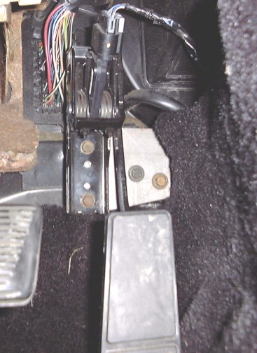
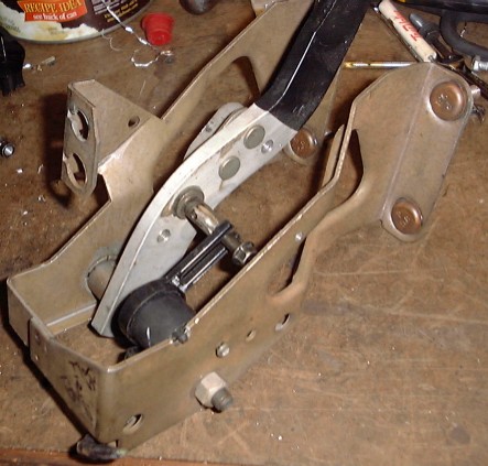
Installed the APP (accel pedal position) sensor and gas pedal assy...
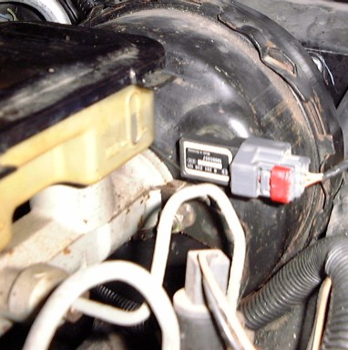
The ECM on this engine also wants to see a BVB (brake vacuum booster) pressure sensor. I presume it is primarily used for the flight recorder function present in these newer GM vehicles. The brake booster had to be removed from the car so I could drill the hole for it and make sure the metal shavings didn't fall down inside the booster.
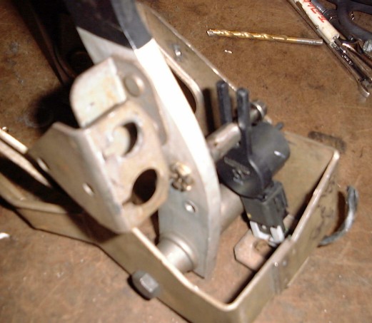
The ECM and TCM receive a stop lamp switch signal directly from the BCM. The BCM activates the stop lamp switch output to turn on the brake lights when a certain signal is seen coming from a sensor mounted on the brake pedal assy. The brake pedal position (BPP) sensor works much the same as a throttle position sensor in that it has a lever actuated by movement of the brake pedal. Mating the BPP sensor to the Fiero brake pedal is easy as long as you can find a location where it won't interfere with the brake linkage or steering column which passes very close to the brake pedal hardware. I found such as location as noted in the pictures below...
The ECM on this engine also wants to see a BVB (brake vacuum booster) pressure sensor. I presume it is primarily used for the flight recorder function present in these newer GM vehicles. The brake booster had to be removed from the car so I could drill the hole for it and make sure the metal shavings didn't fall down inside the booster.
The ECM and TCM receive a stop lamp switch signal directly from the BCM. The BCM activates the stop lamp switch output to turn on the brake lights when a certain signal is seen coming from a sensor mounted on the brake pedal assy. The brake pedal position (BPP) sensor works much the same as a throttle position sensor in that it has a lever actuated by movement of the brake pedal. Mating the BPP sensor to the Fiero brake pedal is easy as long as you can find a location where it won't interfere with the brake linkage or steering column which passes very close to the brake pedal hardware. I found such as location as noted in the pictures below...
-
Sinister Fiero
- Posts: 665
- Joined: Tue Jun 07, 2005 12:10 pm
- Location: Waterloo, Indiana
- Contact:
The OE exhaust crossover pipe used on this engine is routed very close to the transmission gear shifter shaft and lever; similar to 3800 Series 2 applications. The Pontiac Fiero uses a reverse actuating shifter and cable vs. what is normally found in GM front-drive cars. On the LS4's 4T65-E, the OE shift lever arm faces away from the exhaust crossover pipe. But in the Fiero application, this arrangement will work in reverse due to the inverted shifter workings.
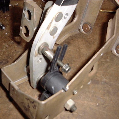
There is not enough room to use a shift lever arm on the opposite side of the shifter shaft (facing the exhaust). The OE Fiero shifter cable is not long enough to loop it around and make it come in behind the shifter shaft so it would work properly with the OE shift arm. So the solution would be to revert the shift cable actuation by building a pivot plate as seen below...
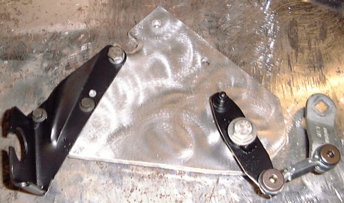
The major components used to build this pivot plate are 5/16" thick aluminum plate, pivot material (I used 3/16" steel), and some items from a local hardware store (as shown below):
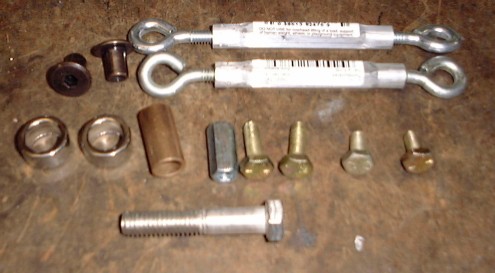
What's pictured above are 2x 1/4" turnbuckles (only used one end out of each turnbuckle; has 1/4-20 thread), 2x 1/2" ID x 3/8" L spacers, 1x 3/8" ID x 1" L brass bushing sleeve, 1x 1/4-20 coupler, 4x 1/4-20 bolts (only needed 2 for my application), 1x 3/8-16 x 2" stainless bolt, and 2x 1/4-20 "end lugs". The end lugs are probably going to be the hardest part to find but my ACE Hardware had them. Basically what they are is a threaded sleeve with a shoulder on one end. It is very important that you get something like this that fits nicely in the end of your turnbuckle eyelets as shown below:
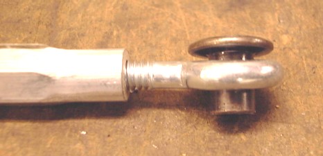
You don't want the lug end fitting tight into the eyelet because it needs to be able to turn in there; but you don't want a lot of slop either. These eyelets aren't welded so I was able to bend them to fit my needs. Make sure you lube up these connections on final assembly to reduce wear. What isn't pictured above is some of the other hardware I had to use assembling this pivot bracket; of which were some 6mm and 8mm bolts used for mounting, some washers used for spacing the pivot arm and eyelet connections, a locking nut used to tighten down the 3/8 stainless bolt used as the pivot shaft, and the shift cable bracket I used for this application.
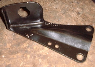
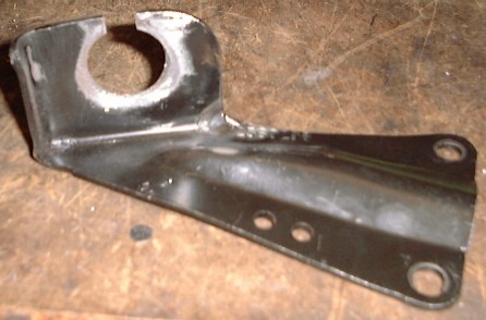
The shift cable bracket I used for this application came from the donor GXP. It's cable opening is too small for the Fiero shifter cable I'm using in this swap which means I had to open up the existing hole to 1" diameter and cut a slot in the top so it matches up to the cable correctly.
Stock:
Modified:
When placing the cable bracket and pivot bolt on the baseplate, the key is to keep your geometry of the shifter arm's arc of motion correct so the full range of gear selections can be made. I used the trial and error method of placement using cardboard mock-ups until I found something that worked. Once finished and installed, it looks like this:
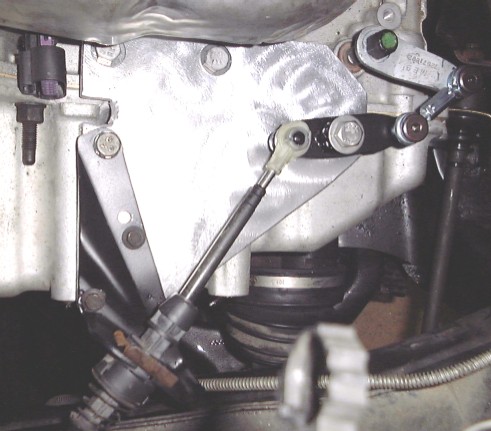
The above design I came up with allows for all ranges of gear selections (P-R-N-D-M) to be accessed using the stock Fiero shifter. I also installed a limiting plate on the Fiero shifter (not shown) to prevent the driver from selecting any gear below the "M" range; which can be done without such a limiter. There are no other lower gear ranges that exist in this TAPShift transmission even though the shifter can be moved there (the transmission will just will remain in "M" range). So the limiter was installed to prevent shifter movement into those other gear selections.
There is not enough room to use a shift lever arm on the opposite side of the shifter shaft (facing the exhaust). The OE Fiero shifter cable is not long enough to loop it around and make it come in behind the shifter shaft so it would work properly with the OE shift arm. So the solution would be to revert the shift cable actuation by building a pivot plate as seen below...
The major components used to build this pivot plate are 5/16" thick aluminum plate, pivot material (I used 3/16" steel), and some items from a local hardware store (as shown below):
What's pictured above are 2x 1/4" turnbuckles (only used one end out of each turnbuckle; has 1/4-20 thread), 2x 1/2" ID x 3/8" L spacers, 1x 3/8" ID x 1" L brass bushing sleeve, 1x 1/4-20 coupler, 4x 1/4-20 bolts (only needed 2 for my application), 1x 3/8-16 x 2" stainless bolt, and 2x 1/4-20 "end lugs". The end lugs are probably going to be the hardest part to find but my ACE Hardware had them. Basically what they are is a threaded sleeve with a shoulder on one end. It is very important that you get something like this that fits nicely in the end of your turnbuckle eyelets as shown below:
You don't want the lug end fitting tight into the eyelet because it needs to be able to turn in there; but you don't want a lot of slop either. These eyelets aren't welded so I was able to bend them to fit my needs. Make sure you lube up these connections on final assembly to reduce wear. What isn't pictured above is some of the other hardware I had to use assembling this pivot bracket; of which were some 6mm and 8mm bolts used for mounting, some washers used for spacing the pivot arm and eyelet connections, a locking nut used to tighten down the 3/8 stainless bolt used as the pivot shaft, and the shift cable bracket I used for this application.
The shift cable bracket I used for this application came from the donor GXP. It's cable opening is too small for the Fiero shifter cable I'm using in this swap which means I had to open up the existing hole to 1" diameter and cut a slot in the top so it matches up to the cable correctly.
Stock:
Modified:
When placing the cable bracket and pivot bolt on the baseplate, the key is to keep your geometry of the shifter arm's arc of motion correct so the full range of gear selections can be made. I used the trial and error method of placement using cardboard mock-ups until I found something that worked. Once finished and installed, it looks like this:
The above design I came up with allows for all ranges of gear selections (P-R-N-D-M) to be accessed using the stock Fiero shifter. I also installed a limiting plate on the Fiero shifter (not shown) to prevent the driver from selecting any gear below the "M" range; which can be done without such a limiter. There are no other lower gear ranges that exist in this TAPShift transmission even though the shifter can be moved there (the transmission will just will remain in "M" range). So the limiter was installed to prevent shifter movement into those other gear selections.
While Ryan continues to display both his high attention to detail and ridiculous skill level with this swap, I will continue to share the 'easy stuff' that I've asked/persuaded him to do as part of the build...Originally posted by blkcofy:
From all the pictures, you can also see the 4TE65hd transmission safely tucked away inside. Which means it's in there for good!! I haven't seen any final pictures of the engine installed in the bay, but I'm sure that's coming once Ryan makes his way from the underside of the car and back into all the HARD stuff.
Oh, I also had to make a tire/wheel purchase this week. Based on the size of the rotors and using the brake calipers from an 88' Fiero, there's no way my OEM 15s were going to fit. Ryan tried, but he would have had to drastically alter the rims. I'll have these up for sale somewhere, as I can't use them at all with the new 'vette rotors.
I ended up going with a 17/18 staggered wheel setup using the Motegi SP7 wheels and I read up on the pros of the new Nexen N3000 tires, and went with those as well.
BLKCOFY

As you can see above, the 2005 LS4 engine has finally found it's permanent home in the newly tagged Fiero GXP. Ryan still needs to complete the complicated wiring and tuning work and install a custom air induction system before he attempts it's first start, but has managed to keep my anxious nature at bay by squeezing in time to complete Rockcrawl's (Fiero Addiction) 12" Corvette Brake Kit and steel braided brake lines from The Fiero Store and my rim & tire setup...

I ended up going with the staggered 17x8/18x9 setup, using 225/17s up front and 265/18s in back, both using 40mm offset rims. Ryan reports that the back tires have plenty of clearance with my coilover springs and struts...which is making me wonder if I should have gone with 275s instead! The following two pictures show the wheels on the car, but still up on jacks as Ryan still has the exhaust system to complete, where he is doing a custom setup using C5 Corvette exhaust tips. With the lowering springs installed, my expectation is that there will little to no tire/fender gap once the car is lowered.


I was a bit worried about my rim choice at first, but seeing them on the car behind those huge rotors, I'm actually quite pleased...quite pleased indeed! :thumbleft:

This is where Ryan and I differ. Ryan double checks everything, and finishes up everything including the small stuff, before starting it. I start it when none of this is complete, so I can figure out what I f*cked up :scratch:blkcofy wrote: Ryan still needs to complete the complicated wiring and tuning work and install a custom air induction system before he attempts it's first start
And when it won't idle, I want to blame it on Ryan's chip. But alas, I don't have an intake, don't have an exhaust, don't have an O2 reading, don't have an IAT reading, and only God knows what else...lol
88GT 3.4 DOHC Turbo
Gooch wrote:Way to go douche. You are like a one-man, fiero-destroying machine.