Real tech discussion on design, fabrication, testing, development of custom or adapted parts for Pontiac Fieros. Not questions about the power a CAI will give.
Atilla the Fun wrote:Getrags have one other failure point. In the bellhousing area, that flat pad at about the 10:00 position. The bearing inside of there can push through.
I've seen that happen, but I think that's a casting defect related to the shape of the structure around that area.
The axial load from the final drive mesh actually pushes the output shaft the OTHER way, away from the part that breaks. The only way to apply load to that part of the case is to dump the clutch in reverse.
Humm I think I see a dog cut box as the next step.
I have seen what atilla fun is talking about, wouldn't that be more likely from downshifting instead of dumping the clutch in reverse? Just saying..
And now that you say that I remeber something from Jon and the indy project, how they ended up getting straight cut gears.
But wouldnt the 2nd gear cluster want to go out the otherside? Or are you saying that the bellhousing side of the case is just so waek that fails there before it can anywhere else?
The DSM trans is similar, and the only place they fail is between 1 and 2 clusters. Hence my bracing thought.
I've got 3 NOS getrags to experiment with, as I figured that and the axles are going to have a short life span.
mrsleeve91 wrote:Humm I think I see a dog cut box as the next step.
I have seen what atilla fun is talking about, wouldn't that be more likely from downshifting instead of dumping the clutch in reverse? Just saying..
And now that you say that I remeber something from Jon and the indy project, how they ended up getting straight cut gears.
But wouldnt the 2nd gear cluster want to go out the otherside? Or are you saying that the bellhousing side of the case is just so waek that fails there before it can anywhere else?
The DSM trans is similar, and the only place they fail is between 1 and 2 clusters. Hence my bracing thought.
I've got 3 NOS getrags to experiment with, as I figured that and the axles are going to have a short life span.
The diff gets pushed toward the bellhousing side due to the angle cut into the gears. That's why the reinforcement you made should be on the other side.
The failure inside the bellhousing area that is referenced in the pic above is a different point of failure... its uncommon and there doesn't seem to be a consensus on why it happens.
Yeah I get that, All im saying is that with every action (force) there is and equal and opposite reaction (force). So if there is enough force to push the diff out of the case on the bell housing side there has to be the same force pushing the 2nd gear cluster towards the drivers side. But cause the bell side is weaker than the drivers it comes out the bell side. Thats Ill I was trying to say.
Also i was thinking that brace cant hurt, so when I grenade this one, Ill figure out why, and fix it for the next one. And when that one fails Ill figure that one out and go from there. trial and error thats all you can do.
mrsleeve91 wrote:there has to be the same force pushing the 2nd gear cluster towards the drivers side. But cause the bell side is weaker than the drivers it comes out the bell side.
Say what? :scratch:
Series8217 wrote:Does the output shaft get pushed toward the input shaft or is that force balanced by the transfer of power to the diff gear?
The diff is pushed to the right. The input shaft is pushed to the left. The output has a force to the right from the input shaft and a force to the left from the diff. Only the NET of these two forces act on the output.
I don't have the center distance between the output shaft and diff handy, but if I did, I could do a BOTEC and figure out which way the output is pushed. Assuming an equal helix angle, I'd guess the output is pushed to the left, because the tooth loading on the final drive mesh is MUCH higher than the tooth loading on the shifted gears.
All Im saying is there has to be the same force pushing on the 2nd cluster in the opposite direction as the way the diff comes out, right?
ok Im done explaining myself. You have made a valid ponit and I will take it into considersation to make another brace.
Ive helped friends with several different managment systems and the best (while complicated ) is Wolf 3D. I have the V4+.
Sorry Atilla fun, the trans you sent me in my my friends white Fiero now. Mine came off egay.
So on with the pics! :thumbleft:
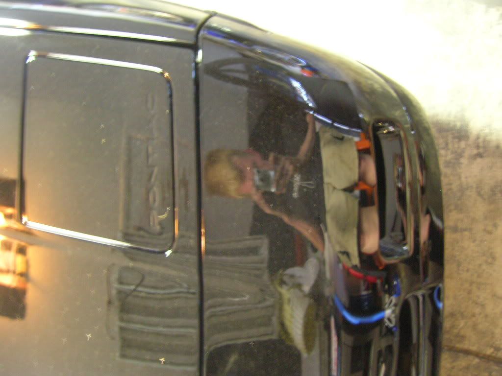
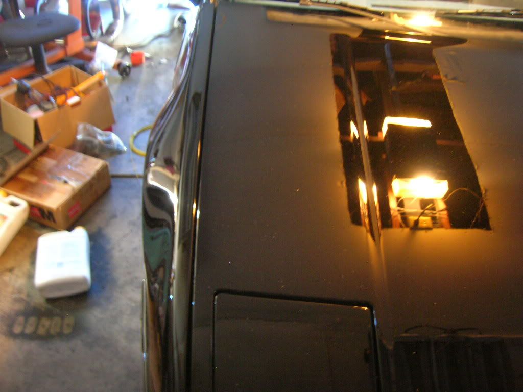
Bringing it home from the body shop
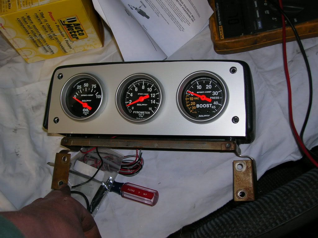
Oil pressure, boost and EGT in this one
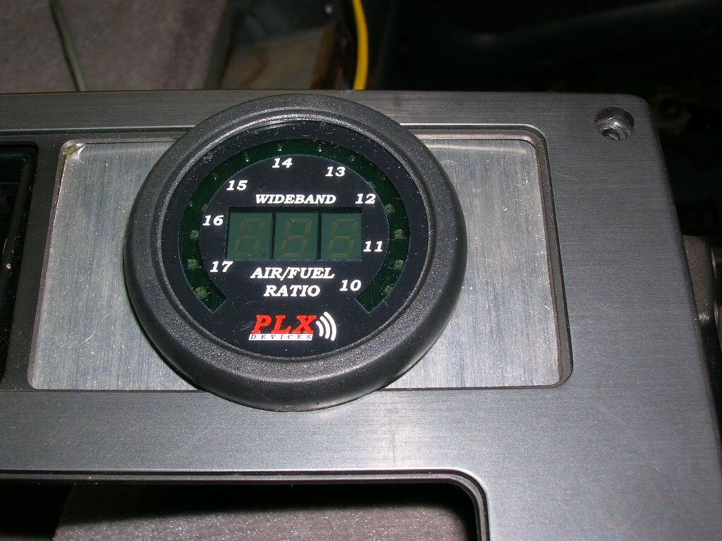
And my W/B o2
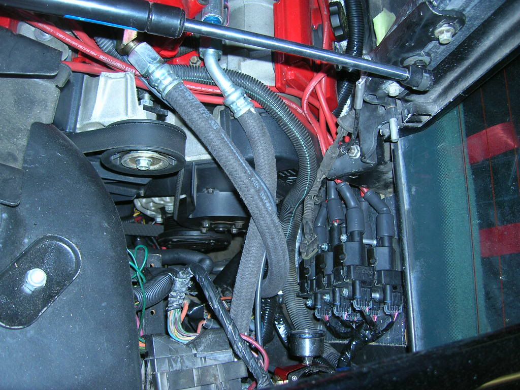
LS2 coil packs
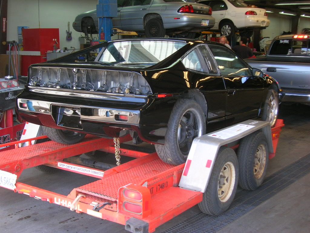
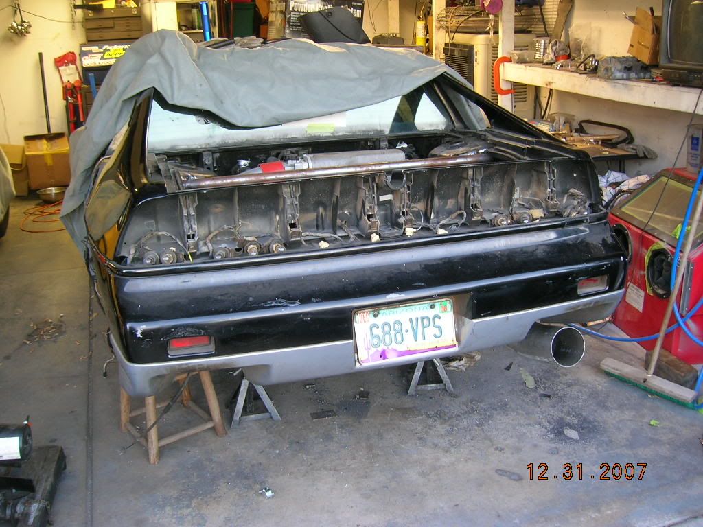
Before paint, just funny, A Fiero with 5" exhaust
mrsleeve91 wrote:there has to be the same force pushing the 2nd gear cluster towards the drivers side. But cause the bell side is weaker than the drivers it comes out the bell side.
Say what? :scratch:
Series8217 wrote:Does the output shaft get pushed toward the input shaft or is that force balanced by the transfer of power to the diff gear?
The diff is pushed to the right. The input shaft is pushed to the left. The output has a force to the right from the input shaft and a force to the left from the diff. Only the NET of these two forces act on the output.
I don't have the center distance between the output shaft and diff handy, but if I did, I could do a BOTEC and figure out which way the output is pushed. Assuming an equal helix angle, I'd guess the output is pushed to the left, because the tooth loading on the final drive mesh is MUCH higher than the tooth loading on the shifted gears.
I would say so too. It doesn't seem the input shaft is designed for very strong thrust loads. It just has a big ball bearing at one end. No flat roller bearing like the output shaft.
Series8217 wrote:
I would say so too. It doesn't seem the input shaft is designed for very strong thrust loads. It just has a big ball bearing at one end. No flat roller bearing like the output shaft.
Both the output and input have sealed bearings that can take thrust loads at the outer ends, and flat rollers that don't care much about axial load or position at the inner ends.
On the bellhousing end of the case they're the same; just roller bearings that can only control axial loads. At the case end, the input shaft has a round ball bearing on that controls thrust and axial loads. The output shaft has the addition of a flat roller thrust bearing with the rollers oriented radially... the input shaft doesn't have that..
I haven't used the aftermarket bearings in a rebuild yet, so all the bearings I've dealt with have been the completely sealed stock variety and I don't know what's in them.
On the 3.61 boxes there is a needle thrust bearing between 1st gear and the FD pinion. This is swapped in 3.94 boxes for a thrust washer.
Sure sounds like the Germans are expecting higher axial loads on the output shaft.
Series8217 wrote:Yeah that's the thrust bearing I was thinking of. The one between the pinion and the idler for 1st.
Yeah, I don't really get all those needles in the box. When they're spinning there's no load on them and when they're loaded, they're not spinning, so it's a pretty easy life for a bearing.