**Been a while since I have had much to say on here about my own car because its been just sitting around. Getting school finished and my career established, along with just life getting in the way of having time to play with my own cars are a few things that have kept my project from progressing. Now I am able to really focus working on this project.**
I was planning on using this as a track event car with a full roll cage, harnesses, race seats and lexan windows. I may not go that extreme after realizing the amount of time spent on the track will be little because the Northwest hates dry track days, even in summer.
I was planning on using the roll cage as the main stiffening addition to the Fiero's chassis but I may not do a cage so I want to stiffen this thing using other, more street able methods available.
I have done quite a few searches and people have ideas how to stiffen the chassis but no one KNOWS what the real world result is.
I like the idea of stripping the chassis bare, adding stitch welds where the different chassis panels come together, adding tubing to triangulate the open sections of the chassis and adding gussets to points where tubing is not a viable option(across the windshield, over the engine) but I don't want to add things in because they "look" like they would make a difference.
I want to do before and after testing to see how much it helps, what doesn't work and what does work.
I have seen pictures of chassis's being measured for torsional rigidity by the use of a known lever arm, a known weight and a dial indicator taking measurement of flex. These are usually on tube frame type vehicles and its easy to find two frame rails to twist with a long lever arm. The Fiero chassis doesn't have this arrangement.
Where do you guys think some good areas on the chassis would be to attach a lever arm(steel tube)that will twist the chassis to measure is torsional rigidity?
Any ideas are welcome guys, would love to be able to actually measure the effects of stitch welding the fiero chassis in certain areas, how bracing in the front and rear compartments affect the rigidity and if its worth it or not to try to stiffen up the space frame at all.
Measuring Chassis Torsional Rigidity
Moderators: The Dark Side of Will, Series8217
-
teamlseep13
- Posts: 430
- Joined: Thu Jul 07, 2005 1:28 am
- Location: Seattle, WA
- Contact:
Measuring Chassis Torsional Rigidity
1988 Pontiac Fiero
Ecotec swap taking much too long...
Ecotec swap taking much too long...
-
The Dark Side of Will
- Peer Mediator
- Posts: 15630
- Joined: Wed Nov 24, 2004 11:13 pm
- Location: In the darkness, where fear and knowing are one
- Contact:
Re: Measuring Chassis Torsional Rigidity
I think I've read somewhere that the Fiero was in the 5k ftlbs per degree range, but that was a LONG time ago. That's better than its contemporary cars, but not that great.
The only viable way to measure torsional stiffness in a way that's meaningful for a test program designed to increase torsional stiffness is by using the load paths that the body sees in use. IE, you will have to introduce the loads where they are seen when the car's on the road.
I think the best way to do that would be with two pillars from the floor into the rear strut towers. They'd need to bolt into the strut towers. One would see tension, the other compression.
At the front end, bolt a box beam in place of the front suspension crossmember. Support one end, hang weight from the other.
I think there are potential gains from triangulating the front and rear compartments, BUT the passenger compartment in between may be so flexible that stiffening the front and rear compartments may not have significant impact.
Take LOTS of pictures and document all your mods/welds!
-
teamlseep13
- Posts: 430
- Joined: Thu Jul 07, 2005 1:28 am
- Location: Seattle, WA
- Contact:
Re: Measuring Chassis Torsional Rigidity
Was waiting for Will to post, seems he is one of the only ones to bite on posts like these...
5000 ftlbs per degree, isn't as bad as I thought it might be but I have searched for a source and no one has anything I can find.
Found lots of Lotus cars specs though.
I know that I will have to use the suspension load points(struts and shocks) to load the chassis as this is where all weight transfer goes through.
The rear seems easy enough to bolt a fixture to the rear struts but the front is the tricky part...a beam hanging front the front cradles place makes sense but I would like to keep the front cradle in place for a more accurate test right? I guess its not technically part of the chassis.
The passenger compartment will be tricky. I was thinking that fully boxing the bottom of the central tunnel would be cool to pull off but where the hell do i put the fuel tank, or do i make myself drop the engine cradle to pull the tank out from the back?
The front of the center tunnel could have a shear panel installed, same with the rear and may allow fuel tank removal from the bottom....
Another idea is a X beam across the front of the passenger compartment well forward of any occupants...
Any other ideas about possible mods to perform or plans for a structure to bolt the car to in order to carry out some testing? Keep em coming!
1988 Pontiac Fiero
Ecotec swap taking much too long...
Ecotec swap taking much too long...
Re: Measuring Chassis Torsional Rigidity
At least on the 88's, I would consider the front crossmember to be a structural component. It is quite beefy and the 8 mounting bolts are spread out on the front frame rails. To test an 88, I would pull the lower a-arms off and mount the beam via the lower a-arm mounting tabs.
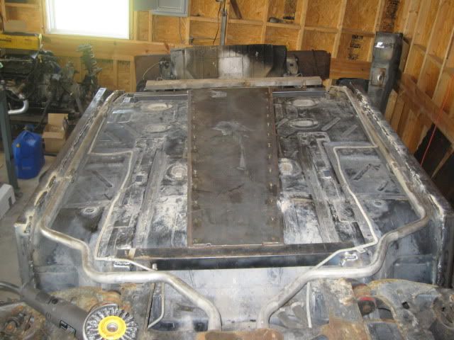
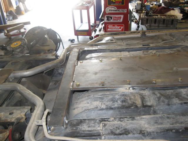
I am all for making the center tunnel more structural. The bottom can be capped with a some angle welded to the floor pan to give a nice flat attachment point, the angle is also welded to additional crossmembers that tie into the lower portions of the front/rear frame rails. Then a sheet is bolted to the bottom to... The fuel tank stays in the stock location and is still removable... Something like this:
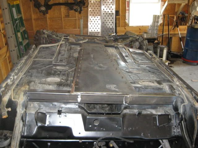
I would also suggest doing something to the top side of the center console to bring the structure up as high as possible and to widen it at the front and try to tie it into the base of the A-pillars if possible. You could even recreate the shape of the stock center console (ECM cover) and dash with structural components to help carry the loads through the passenger compartment. The front of the center tunnel is quite small/tiny and doesn't do much to spread the load. Here is a picture of how small it gets in the front:
Once you beef up the center console area, then you could add a link connecting each strut tower to the back side of the reinforced center console. The reinforced dash would connect to the base of the a-pillars.
If you have a fast back car, you can run some tubing inside the c-pillars to directly connect the roofline to the rear upper frame rails/top of stut towers.
I am all for making the center tunnel more structural. The bottom can be capped with a some angle welded to the floor pan to give a nice flat attachment point, the angle is also welded to additional crossmembers that tie into the lower portions of the front/rear frame rails. Then a sheet is bolted to the bottom to... The fuel tank stays in the stock location and is still removable... Something like this:
I would also suggest doing something to the top side of the center console to bring the structure up as high as possible and to widen it at the front and try to tie it into the base of the A-pillars if possible. You could even recreate the shape of the stock center console (ECM cover) and dash with structural components to help carry the loads through the passenger compartment. The front of the center tunnel is quite small/tiny and doesn't do much to spread the load. Here is a picture of how small it gets in the front:
Once you beef up the center console area, then you could add a link connecting each strut tower to the back side of the reinforced center console. The reinforced dash would connect to the base of the a-pillars.
If you have a fast back car, you can run some tubing inside the c-pillars to directly connect the roofline to the rear upper frame rails/top of stut towers.
-
The Dark Side of Will
- Peer Mediator
- Posts: 15630
- Joined: Wed Nov 24, 2004 11:13 pm
- Location: In the darkness, where fear and knowing are one
- Contact:
Re: Measuring Chassis Torsional Rigidity
The C5 & C6 Corvettes use a bolt-in panel to close off their driveline/exhaust tunnels to increase chassis stiffness.
I think that the front and rear frame rails do not tie in to the center tunnel very well. To make the center tunnel contribute better to the stiffness of the body, it needs to be tied into the front and rear frame rails better... The Fiero is not very good as a backbone chassis.
I think that the front and rear frame rails do not tie in to the center tunnel very well. To make the center tunnel contribute better to the stiffness of the body, it needs to be tied into the front and rear frame rails better... The Fiero is not very good as a backbone chassis.
-
teamlseep13
- Posts: 430
- Joined: Thu Jul 07, 2005 1:28 am
- Location: Seattle, WA
- Contact:
Re: Measuring Chassis Torsional Rigidity
Fieroguru, where did you get those pics?
I agree that using the front cradle installed seems like the most real world test because it transmits all the suspension loads to the rest of the chassis.
The center tunnel shear panel is on the list to test, its execution is something entirely different. A bolted on panel like the Y body's makes the most practical sense but they had a that in the original design plans and it may not pan out as a real stiffener in the Fiero, though testing will tell.
Will, how would you attach the front and rear cradles more effectively to the frame rails?
The rear cradle begs for more than 4 attachment bolts. The front of the cradle could tie to the center of the chassis if it had a rail from its center to the rear structure of the center tunnel....
I may have to get out some balsa wood and make some mock up mini fieros before I start buying steel. Besides the facotry service manual, does anyone have any chassis drawings to scale?
I am not on Old Europe enough to know if someone has does this already...
Thanks guys!
1988 Pontiac Fiero
Ecotec swap taking much too long...
Ecotec swap taking much too long...
Re: Measuring Chassis Torsional Rigidity
The under panel pics are mine from a roadster I was helping to build. I have quite a few more.teamlseep13 wrote:Fieroguru, where did you get those pics?
The other pic is from another friends roadster build with quite a bit of reinforcement including connecting the front/rear frame rails through the floor pan area. I have a few more pics of that setup as well, but it was not setup to retain the stock fuel tank area.
-
The Dark Side of Will
- Peer Mediator
- Posts: 15630
- Joined: Wed Nov 24, 2004 11:13 pm
- Location: In the darkness, where fear and knowing are one
- Contact:
Re: Measuring Chassis Torsional Rigidity
If the lever arm used on the front picks up all four of the vertical bolts on an '84-'87 car or the four "main" bolts on an '88 car, that's probably about as good as it's going to get.
The '88 crossmember really shouldn't link the two frame rails together very well in torsion or bending due to the small cross section in the middle where the coolant pipes pass under it.
The '88 crossmember really shouldn't link the two frame rails together very well in torsion or bending due to the small cross section in the middle where the coolant pipes pass under it.
Re: Measuring Chassis Torsional Rigidity
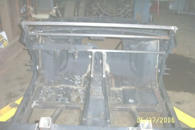
Here is a pic of an 88 chassis I was cutting up. I removed the center section to save it for reference in a later fuel tank build, but you can see the tube portions at both ends of the center tunnel that tie into the frame rails. A couple of the issues with these tubes is that they are only along the top side and the connection at the front between the tunnel and this tube is rather narrow. On the roadster build above, I added additional tubing at the bottom side of the tunnel front/rear to help overcome the stock tubes being only at the top.The Dark Side of Will wrote:The C5 & C6 Corvettes use a bolt-in panel to close off their driveline/exhaust tunnels to increase chassis stiffness.
I think that the front and rear frame rails do not tie in to the center tunnel very well. To make the center tunnel contribute better to the stiffness of the body, it needs to be tied into the front and rear frame rails better... The Fiero is not very good as a backbone chassis.
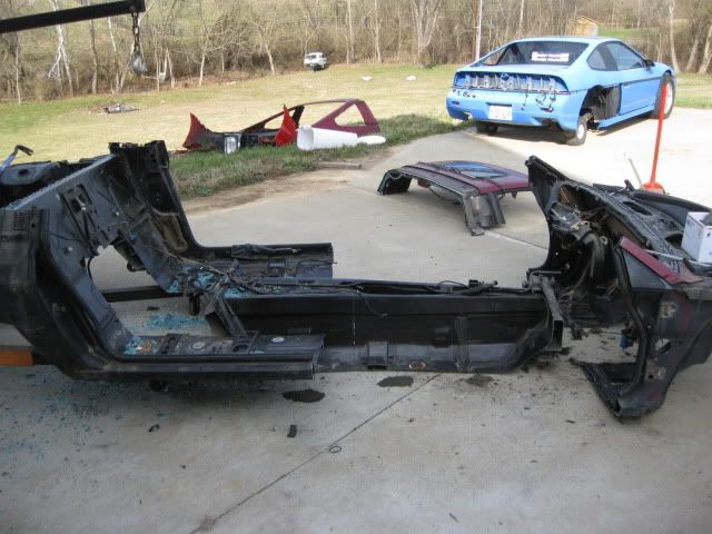
The center section is now in the garage and I can take a better pic of it if needed.
-
The Dark Side of Will
- Peer Mediator
- Posts: 15630
- Joined: Wed Nov 24, 2004 11:13 pm
- Location: In the darkness, where fear and knowing are one
- Contact:
Re: Measuring Chassis Torsional Rigidity
What happens when the body is in torsion?
The frame rail on one side is pushed up and the rail on the other side is pushed down. In a backbone body, the torsional stiffness of the lateral connection from the frame rails to the back bone is very important. There isn't much to that connection in a Fiero. It's similar to why a drop-down in the middle of a sway bar dramatically reduces the stiffness of the bar.
The Fiero, as a backbone body, is pretty lousy for exactly that reason. It can't make up its mind whether it's a perimeter frame or backbone and doesn't do either one very well.
The overall result is better than many of its contemporaries (but which happen to be lighter bodies...), but not great by modern standards.
-
teamlseep13
- Posts: 430
- Joined: Thu Jul 07, 2005 1:28 am
- Location: Seattle, WA
- Contact:
Re: Measuring Chassis Torsional Rigidity
Any pics are appreciated!
The lack of ties ins from the frame rails to the lower part of the center tunnel seem to a be a weak point, theorectically.
How to effectively make that center tunnel a closed box is the real question.
Haven't made a huge amount of progress on a fixture for measuring stiffness, I got a new welder so I have been playing with that but I will be doing something this spring for sure.
Thanks guys!
1988 Pontiac Fiero
Ecotec swap taking much too long...
Ecotec swap taking much too long...