CAD Stuff

A place for fun discussion of common interests we have besides Fieros

Moderator: ericjon262

ericjon262
Posts: 2824
Joined: Mon May 24, 2010 5:34 pm
Location: Aiken, SC

CAD Stuff

Post by ericjon262 »

I thought I'd start a thread of CAD stuff, that I've drawn and am working on. most of it is now being done with Onshape, I have done some with google Sketchup, but it was just too buggy for the stuff I want to do. so far, as I learn the ropes with it, Onshape appears to be a pretty awesome program for what I need.

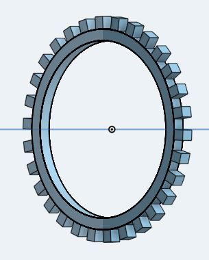
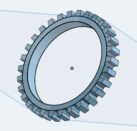
the early goes at a VSS reluctor:
vss reluctor.png
vss reluctor.png (37.07 KiB) Viewed 6144 times
vss reluctor.png
vss reluctor.png (67.4 KiB) Viewed 6146 times
A later run:
vss reluctor 3 way.png
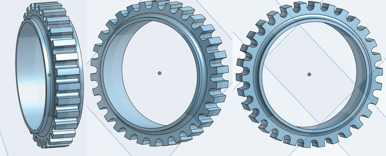
vss reluctor 3 way.png (397 KiB) Viewed 6146 times
My C5 to 88 Fiero rear brake caliper adapter:
brake.jpg
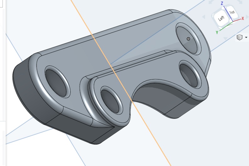
brake.jpg (70.3 KiB) Viewed 6146 times
some stuff from the Sketchup days

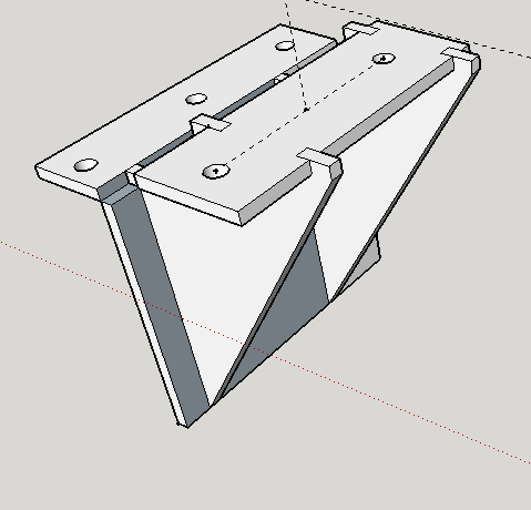
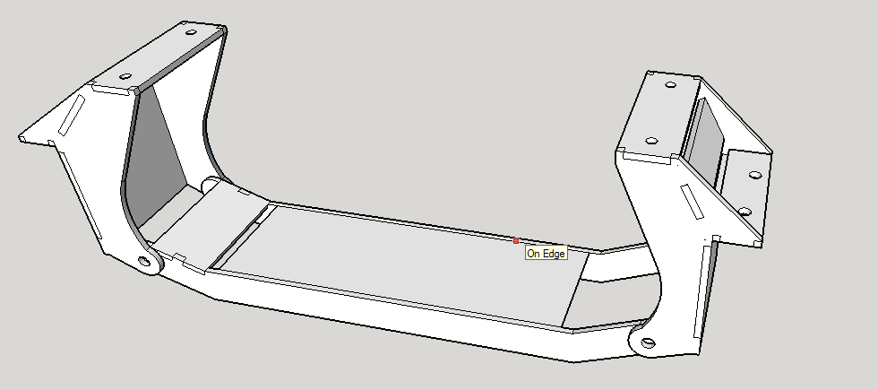
Motor mounts/crossmembers to install a Envoy 4.2 inline six into a 70 GMC:
mounts.png
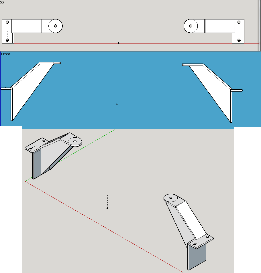
mounts.png (26.58 KiB) Viewed 6146 times
mount revised.png
mount revised.png (16.23 KiB) Viewed 6146 times
mount 2.0.png
mount 2.0.png (16.38 KiB) Viewed 6146 times
mount final.png
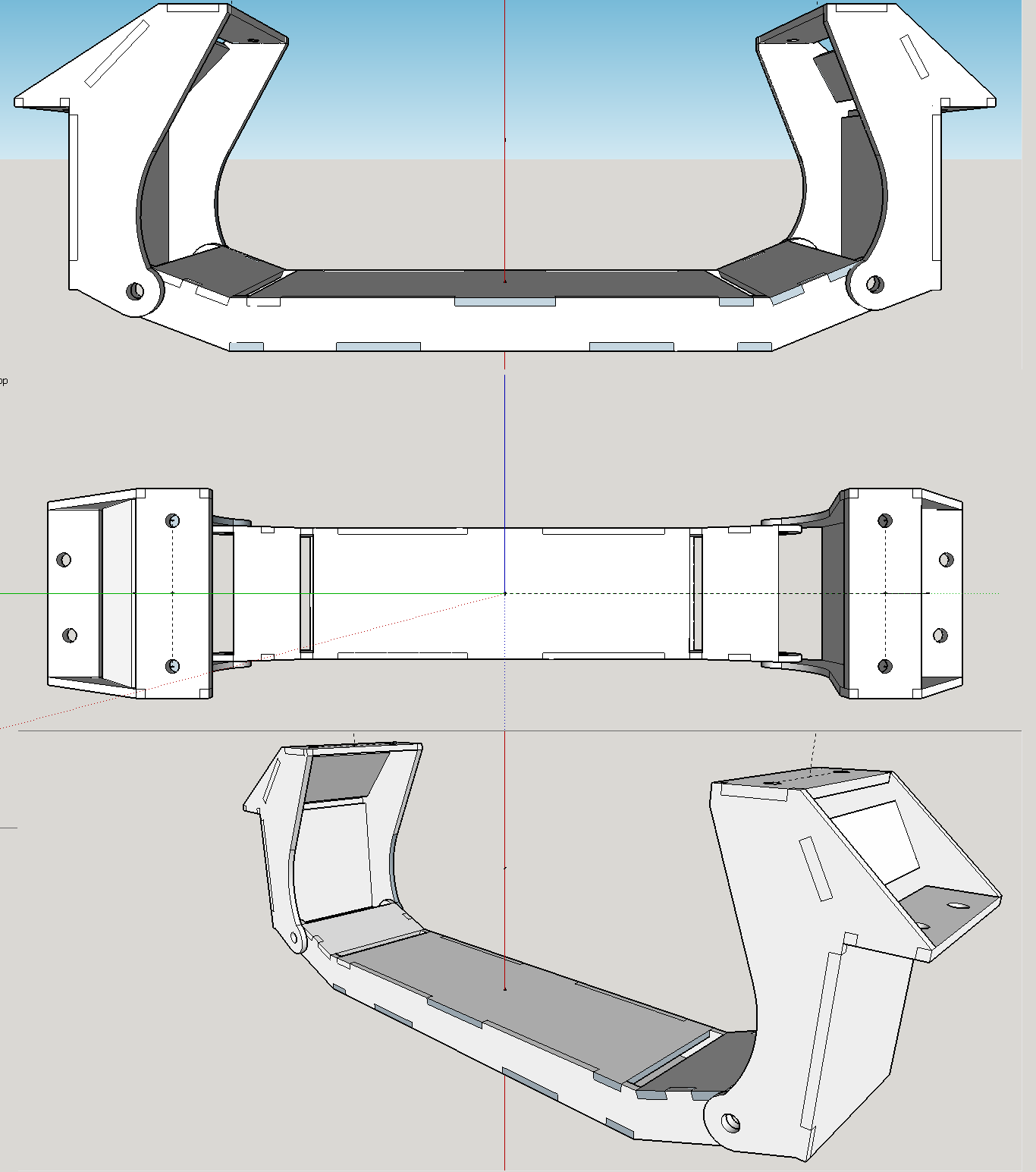
mount final.png (57.39 KiB) Viewed 6146 times
and header I was drawing up, designed to be made with weld el's:
header2.png
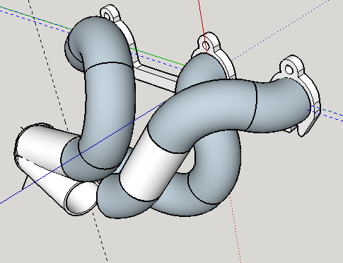
header2.png (55.26 KiB) Viewed 6146 times
header1.png
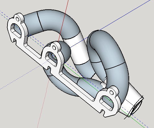
header1.png (68.85 KiB) Viewed 6146 times
hopefully, in the next year, I'll be picking up a 3d printer that I can start prototyping some of my ideas with, if/when that happens, I'll start posting both drawings, and results of them. if you have any request for simple things, I'm more than willing to take a crack at them, I'd like to gain more experience, I learned quite a bit with that reluctor wheel.
"I am not what you so glibly call to be a civilized man. I have broken with society for reasons which I alone am able to appreciate. I am therefore not subject to it's stupid laws, and I ask you to never allude to them in my presence again."
ericjon262
Posts: 2824
Joined: Mon May 24, 2010 5:34 pm
Location: Aiken, SC

Re: CAD Stuff

Post by ericjon262 »

3x00 rocker pedestals. I drew these for practice.
rocker stand.png
rocker stand.png (110.62 KiB) Viewed 6140 times
3x00 header flange, 1/2" thick. this was a bit trickier than you might think, nothing is square, and my caliper isn't quite big enough to take each measurement.
3x00 flange.png
3x00 flange.png (68.88 KiB) Viewed 6140 times
I'm also playing around with a 3d scanner app on my phone, it appears to work ok, but to get truly good results, I'll need a larger, clear space, and, to get the best results, I think some parts will need to be thoroughly cleaned and blasted, and maybe even painted with contrasting colors to obtain the most crisp model. more to follow.
Last edited by ericjon262 on Sat Jan 19, 2019 5:01 pm, edited 1 time in total.
"I am not what you so glibly call to be a civilized man. I have broken with society for reasons which I alone am able to appreciate. I am therefore not subject to it's stupid laws, and I ask you to never allude to them in my presence again."
The Dark Side of Will
Peer Mediator
Posts: 15626
Joined: Wed Nov 24, 2004 11:13 pm
Location: In the darkness, where fear and knowing are one
Contact:

Re: CAD Stuff

Post by The Dark Side of Will »

24V Swap crossmember for AWD BMW E30 under development:
The Dark Side of Will wrote: Sun Jul 22, 2018 2:51 pm PIMA:

Image
The Dark Side of Will wrote: Sun Sep 09, 2018 12:31 pm Finally starting to look like something I can really use:

Image
The Dark Side of Will wrote: Sun Sep 09, 2018 2:44 pm And after even more work, I think I have the steering rack, tie rods, rack boots and engine mount towers deconflicted.
Now I need to update the front bulkhead to free up dynamic clearance for the sway bar, but that can wait for another day.

Image
Engine mounts for a Small Block Chevy into an AMC Eagle:
The Dark Side of Will wrote: Sun Sep 16, 2018 6:01 pm
I updated the CAD with the results of today's test fit.

Image
The Dark Side of Will wrote: Making progress. This is the right side mount assembly. The gold and dark blue parts are for the disco housing and the "large" non-disco housing. They'd be 1" longer for the small non-disco housing.
Once this is made and fit checked I'll be able to start on the snout bracket.

Image
ericjon262
Posts: 2824
Joined: Mon May 24, 2010 5:34 pm
Location: Aiken, SC

Re: CAD Stuff

Post by ericjon262 »

I see we both use some similar design ideas. interlocking flat plates are easier to setup and weld compared to non interlocking.
"I am not what you so glibly call to be a civilized man. I have broken with society for reasons which I alone am able to appreciate. I am therefore not subject to it's stupid laws, and I ask you to never allude to them in my presence again."
ericjon262
Posts: 2824
Joined: Mon May 24, 2010 5:34 pm
Location: Aiken, SC

Re: CAD Stuff

Post by ericjon262 »

working on an image based 3D scanner. the round part is a turntable, the arm has holes every 2 degrees, so the camera can take pictures all the way around. the next big part I have to develop will be the camera holder. the camera is my Cat S60, ATM, but I may try acquire something specifically for it, or maybe even a pair of cameras if I find software support.

Edit: this might be a stillborn project, I'm starting to see there are handheld 3d scanners in the ~$200-400 range, I could very quickly have much more than that tied up in this...
scanner 2.png
scanner 2.png (59.36 KiB) Viewed 6122 times
The scann3d ap was able to generate this rough model based on about 40 pictures, not taken at even intervals or heights, on an uneven, non uniform colored surface. I also have an idea of how to "hide" the turntable from the camera as well.
scann3d.png
scann3d.png (282.81 KiB) Viewed 6122 times
using the rig drawn above, I bet I could make fairly accurate models, with minimal effort, and for way less than the cost of a high quality laser scanner. I could, possibly add the functionality of a laser, with a new mount.
"I am not what you so glibly call to be a civilized man. I have broken with society for reasons which I alone am able to appreciate. I am therefore not subject to it's stupid laws, and I ask you to never allude to them in my presence again."
The Dark Side of Will
Peer Mediator
Posts: 15626
Joined: Wed Nov 24, 2004 11:13 pm
Location: In the darkness, where fear and knowing are one
Contact:

Re: CAD Stuff

Post by The Dark Side of Will »

ericjon262 wrote: Sun Dec 16, 2018 12:35 am I see we both use some similar design ideas. interlocking flat plates are easier to setup and weld compared to non interlocking.
Since fixturing is extra stuff that has to be designed, produced and manufactured, I work toward my products being assemblable with just a magnetic square and the assembly drawing.
The Dark Side of Will
Peer Mediator
Posts: 15626
Joined: Wed Nov 24, 2004 11:13 pm
Location: In the darkness, where fear and knowing are one
Contact:

Re: CAD Stuff

Post by The Dark Side of Will »

ericjon262 wrote: Sun Dec 16, 2018 10:01 pm working on an image based 3D scanner. the round part is a turntable, the arm has holes every 2 degrees, so the camera can take pictures all the way around. the next big part I have to develop will be the camera holder. the camera is my Cat S60, ATM, but I may try acquire something specifically for it, or maybe even a pair of cameras if I find software support.

Edit: this might be a stillborn project, I'm starting to see there are handheld 3d scanners in the ~$200-400 range, I could very quickly have much more than that tied up in this...

scanner 2.png

The scann3d ap was able to generate this rough model based on about 40 pictures, not taken at even intervals or heights, on an uneven, non uniform colored surface. I also have an idea of how to "hide" the turntable from the camera as well.

scann3d.png

using the rig drawn above, I bet I could make fairly accurate models, with minimal effort, and for way less than the cost of a high quality laser scanner. I could, possibly add the functionality of a laser, with a new mount.
I haven't tried the app you mention, but engineering level models from photographs are difficult to produce. One of the key factors is lens abberation, which will have a large impact on any photos taken by a cell phone camera of an object within arm's reach. At the angle shown of your cylinder head model, for example, the length of the part is probably at least 50% of the distance from the close end of the part to the camera, leading to significant image distortion. As an exercise, take photos of graph paper at different distances, then bring them up in paint and look at the pixel coordinates to see how straight the lines are.
ericjon262
Posts: 2824
Joined: Mon May 24, 2010 5:34 pm
Location: Aiken, SC

Re: CAD Stuff

Post by ericjon262 »

The Dark Side of Will wrote: Mon Dec 17, 2018 9:42 am
ericjon262 wrote: Sun Dec 16, 2018 10:01 pm working on an image based 3D scanner. the round part is a turntable, the arm has holes every 2 degrees, so the camera can take pictures all the way around. the next big part I have to develop will be the camera holder. the camera is my Cat S60, ATM, but I may try acquire something specifically for it, or maybe even a pair of cameras if I find software support.

Edit: this might be a stillborn project, I'm starting to see there are handheld 3d scanners in the ~$200-400 range, I could very quickly have much more than that tied up in this...

scanner 2.png

The scann3d ap was able to generate this rough model based on about 40 pictures, not taken at even intervals or heights, on an uneven, non uniform colored surface. I also have an idea of how to "hide" the turntable from the camera as well.

scann3d.png

using the rig drawn above, I bet I could make fairly accurate models, with minimal effort, and for way less than the cost of a high quality laser scanner. I could, possibly add the functionality of a laser, with a new mount.
I haven't tried the app you mention, but engineering level models from photographs are difficult to produce. One of the key factors is lens abberation, which will have a large impact on any photos taken by a cell phone camera of an object within arm's reach. At the angle shown of your cylinder head model, for example, the length of the part is probably at least 50% of the distance from the close end of the part to the camera, leading to significant image distortion. As an exercise, take photos of graph paper at different distances, then bring them up in paint and look at the pixel coordinates to see how straight the lines are.
I was hoping to overcome some of the accuracy problems, with massive amounts of data, 1 picture every 2 degrees rotation (180 pictures), then 45 elevations works out to 8100 pictures, I'd bet that would make a huge difference. along with careful surface prep. that being said. I did pick up a handheld structured light scanner from 3D Sense for $275, I'm looking forward to seeing the results. I'm hoping that I can use it along with my calipers to generate fairly accurate models.
"I am not what you so glibly call to be a civilized man. I have broken with society for reasons which I alone am able to appreciate. I am therefore not subject to it's stupid laws, and I ask you to never allude to them in my presence again."
ericjon262
Posts: 2824
Joined: Mon May 24, 2010 5:34 pm
Location: Aiken, SC

Re: CAD Stuff

Post by ericjon262 »

good news bad news... my scanner showed up! bad news, it won't sync with the software... I'm awaiting a response from the company for troubleshooting, unfortunately, I don't think I'll hear back until after christmas at the earliest...
"I am not what you so glibly call to be a civilized man. I have broken with society for reasons which I alone am able to appreciate. I am therefore not subject to it's stupid laws, and I ask you to never allude to them in my presence again."
ericjon262
Posts: 2824
Joined: Mon May 24, 2010 5:34 pm
Location: Aiken, SC

Re: CAD Stuff

Post by ericjon262 »

I got the scanner to sync, and, so far, I'm not too impressed. I have been attempting to model a bare 3500 cylinder head, with less than favorable results. I have a few tricks up my sleeve I'm going to try and see if I can't step things up a bit. the big thing, is I'm going to try and dull the finish. from what I have read, structured light scanners don't play too nice with shiny surfaces, which the 3500 head has several. I'm also going to try and make a holder for the scanner that will rotate around the part, vice rotating the part. I noticed that when rotating the part, the scanner almost instantly loses track of the part.

the holder will be a simple device, consisting of a square platform, on a pedestal, that comes through a lazy susan that the holder will be mounted too. if I determine it's necessary, I may also add a counterweight to offset the scanner, but I don't think that will be required. the scanner will be held by an arm similar to the one in my scanner pictured above, except it will be taller before arcing towards the center.

I'll post some pictures of the design, and the scans as they currently stand later.
"I am not what you so glibly call to be a civilized man. I have broken with society for reasons which I alone am able to appreciate. I am therefore not subject to it's stupid laws, and I ask you to never allude to them in my presence again."
FieroWanaBe1
Posts: 427
Joined: Sun Mar 11, 2007 11:26 pm

Re: CAD Stuff

Post by FieroWanaBe1 »

I've tried to use my Xbox Kinect (both generations) as scanners with Microsoft and Faro software, the results were less than ideal. Good for overall packaging, bad for hole locations. I assume most low cost scanners are using similar technology.

@preview.jpg
@preview.jpg (250.6 KiB) Viewed 6083 times
@preview.jpg
@preview.jpg (326.68 KiB) Viewed 6083 times
@preview.jpg
@preview.jpg (297.85 KiB) Viewed 6083 times
@preview.jpg
@preview.jpg (418.41 KiB) Viewed 6083 times
car.
ericjon262
Posts: 2824
Joined: Mon May 24, 2010 5:34 pm
Location: Aiken, SC

Re: CAD Stuff

Post by ericjon262 »

I'm having similar results, gives a good general shape, but holes are proving to be problematic. I have a few ideas I am going to try an implement, to get an accurate resolution for hole location. I'm also hoping the scanner holder makes a decent improvement in resolution, I probably won't go super hardcore with designing it, I figure a quick rig will give proof of concept. if I can't get any better accuracy, I may have to go back to the old fashioned way.
"I am not what you so glibly call to be a civilized man. I have broken with society for reasons which I alone am able to appreciate. I am therefore not subject to it's stupid laws, and I ask you to never allude to them in my presence again."
ericjon262
Posts: 2824
Joined: Mon May 24, 2010 5:34 pm
Location: Aiken, SC

Re: CAD Stuff

Post by ericjon262 »

here is one of the first modeled scans I have made, much better than the photometric scan, but still in dire need of help. honestly, I was hoping for much better, I am going to build a rig to hold the scanner, and hopefully that helps. I may also try dulling the surface of the head to a uniform texture and color to see if that helps further improve the results.
head.png
head.png (416.03 KiB) Viewed 6075 times
"I am not what you so glibly call to be a civilized man. I have broken with society for reasons which I alone am able to appreciate. I am therefore not subject to it's stupid laws, and I ask you to never allude to them in my presence again."
Indy
Posts: 992
Joined: Wed Nov 17, 2004 12:22 am
Location: the middle of a wheatfield

Re: CAD Stuff

Post by Indy »

If you have a CUDA enabled NVIDIA GPU, you might give Meshroom a shot. I've used it before with decent results.

https://alicevision.github.io/#meshroom
Indy DOHC Turbo SD4.....someday.
Oh, and f*ck the envelope. (RFT Insurgent)
The Dark Side of Will
Peer Mediator
Posts: 15626
Joined: Wed Nov 24, 2004 11:13 pm
Location: In the darkness, where fear and knowing are one
Contact:

Re: CAD Stuff

Post by The Dark Side of Will »

I was wondering if you'd show up. :good:

I have some more data to put into the BMW crossmember, but just got it and haven't had the time to update the model yet.

The Eagle stuff won't see visibly significant changes as we're just iterating to a perfect fit at this point. We did find out that the very first left mount we had assembled wasn't assembled straight, and thus all the work I'd done on the right mount and snout support was off a bit. The next iteration of parts coming out is updated for the correctly assembled left mount that we have now. Feh.

Edit: Some kind of 3D scanner might or might not have worked, because the interfaces that have to meet are all on opposite sides of the engine & diff, so the relationships of the point clouds in the larger workspace would be hard to nail down.
ericjon262
Posts: 2824
Joined: Mon May 24, 2010 5:34 pm
Location: Aiken, SC

Re: CAD Stuff

Post by ericjon262 »

Indy wrote: Thu Jan 17, 2019 2:06 pm If you have a CUDA enabled NVIDIA GPU, you might give Meshroom a shot. I've used it before with decent results.

https://alicevision.github.io/#meshroom
That's neat, but I don't think I have a powerful enough GPU for anything like that. I'm hoping that after I have the head I was trying to model bed blasted, as well as using a more stable mount for the scanner, that it produces a clearer result.
"I am not what you so glibly call to be a civilized man. I have broken with society for reasons which I alone am able to appreciate. I am therefore not subject to it's stupid laws, and I ask you to never allude to them in my presence again."
ericjon262
Posts: 2824
Joined: Mon May 24, 2010 5:34 pm
Location: Aiken, SC

Re: CAD Stuff

Post by ericjon262 »

I haven't been messing with the scanner much, but I did draw up a new TB flange/adapter.

Image

It's designed to be welded to a 3" OD pipe, and allow an LS4 TB to be attached. there's an O-ring for sealing as well. the groove is designed so the O-ring will be about .050" proud of the flange face. I still need to go back and add threads to the holes for the bolts, but otherwise it's about done unless I change the tube size.

sized for aluminum pipe instead of tube:

Image
"I am not what you so glibly call to be a civilized man. I have broken with society for reasons which I alone am able to appreciate. I am therefore not subject to it's stupid laws, and I ask you to never allude to them in my presence again."
The Dark Side of Will
Peer Mediator
Posts: 15626
Joined: Wed Nov 24, 2004 11:13 pm
Location: In the darkness, where fear and knowing are one
Contact:

Re: CAD Stuff

Post by The Dark Side of Will »

PTC is acquiring OnShape... I wonder if that means OS will get better or worse... Or just more expensive.

On a project note, I have the model & hats for my custom Coleman hats complete. I need to test the stock Mitsu rotor on my mock-up to make sure I don't need to diddle the drum ID a little bit, then I can send it.

The crossmember for Bad Idea BMW has been on hold pending getting Fiero stuff done.

However, I'm also wrapping up the design on an improved wrist roller that could have an appreciable market, so I need to get some drawings made and the prototype produced.

I just bought a Mercedes and may soon be designing spherical bearing shells for all of its suspension pivots.
ericjon262
Posts: 2824
Joined: Mon May 24, 2010 5:34 pm
Location: Aiken, SC

Re: CAD Stuff

Post by ericjon262 »

I paid off my truck, and bought myself a treat...

https://folgertech.com/collections/3d-p ... rinter-kit

shit's gonna get real!
"I am not what you so glibly call to be a civilized man. I have broken with society for reasons which I alone am able to appreciate. I am therefore not subject to it's stupid laws, and I ask you to never allude to them in my presence again."
ericjon262
Posts: 2824
Joined: Mon May 24, 2010 5:34 pm
Location: Aiken, SC

Re: CAD Stuff

Post by ericjon262 »

The Dark Side of Will wrote: Mon Oct 28, 2019 2:09 pm PTC is acquiring OnShape... I wonder if that means OS will get better or worse... Or just more expensive.
I received an email saying that OS would remain free.

The Dark Side of Will wrote: Mon Oct 28, 2019 2:09 pm On a project note, I have the model & hats for my custom Coleman hats complete. I need to test the stock Mitsu rotor on my mock-up to make sure I don't need to diddle the drum ID a little bit, then I can send it.

The crossmember for Bad Idea BMW has been on hold pending getting Fiero stuff done.

However, I'm also wrapping up the design on an improved wrist roller that could have an appreciable market, so I need to get some drawings made and the prototype produced.
Wrist roller?
The Dark Side of Will wrote: Mon Oct 28, 2019 2:09 pm
I just bought a Mercedes and may soon be designing spherical bearing shells for all of its suspension pivots.
don't you have enough on your plate??? lol

:crazy:
"I am not what you so glibly call to be a civilized man. I have broken with society for reasons which I alone am able to appreciate. I am therefore not subject to it's stupid laws, and I ask you to never allude to them in my presence again."
Post Reply