I've been thinking quite a bit about how to design a new pair of UCA's and spindles for my Fiero, I wanted to share thoughts so that hopefully i can develop a part that is very strong, very functional, and use off the shelf wear parts.
the big goals right now:
1. add additional caster to the front suspension. I should quantify this before continuing too much further.
2. use off the shelf parts for all wear parts, to include ball joints, wheel bearings, rod ends ect. off the shelf in this case, will extend to industrial shelves, not just automotive shelves.
3. be strong enough to handle both everyday driving, and track abuse.
4. provide a means of repeatable adjustment for camber
5. provide provisions for a parking brake.
6. minimize outsourcing of machine/fabrication work.
Current parts considerations:
wheel bearings:
C5 'vette
Minivan 5x115
Jeep 5x4.5
As far as I am aware, all of those use the same basic housing dimensions. CV axles and wheels will need to be carefully considered, wheel pattern could have a massive effect on wheel, wheel bearing, and brake rotor pricing.
Parking brake:
C5 'Vette
Will's hot rod parking brake(I don't consider the parking brake shoe a wear part)
Wilwood's new drum in hat setups
I haven't put much effort into defining possibilities for rotors and calipers yet, Overall, I would like to stay 12"+ diameter, and I would prefer a 4 piston rigid mounted caliper, I would like to put effort into finding lightweight calipers and rotors, quick change pads would be a nice plus, but not required.
step 1 should be to gain dimensions of factory 84-87 UCA's, 84-87 spindles, and 88 rear knuckles. The rear will most likely be the simpler side of the puzzle, it's been carefully modeled already thanks to Blooze on old europe, the next step would be to relocate the lateral link pickups to match my lowered ride height, and make the necessary modifications to fit updated brakes and bearings.
step 2 will be to determine which bearings, brake rotors, and calipers. Will has a well thought out parking brake, that meets the requirements I have outlined above, I may consider something similar, or just use a standard C5 parking brake if it fits, thankfully I have a whole C5 rear knuckle to measure off of.
step 3 will be model and prototype, and maybe destructive testing depending on the difficulty of the assembly and fixturing for testing.
step 4, will be a final "production" model, although, I'm not planning an actual production run at this point.
this is just a rough sheet of starting ideas, once I start working on more formal sketches, I'll post them. if you have any ideas i should be considering, I'm open to ideas.
FYI, willwood has nice parts drawings on their website, I'll probably be utilizing some of them. I know McMaster does as well, any other good ones that could be useful for this kind of undertaking? I don't expect this to be fast paced, I have alot on my plate, but it is a project that has been on my mind for a while.
custom chassis/suspension considerations.
Moderators: The Dark Side of Will, Series8217
-
ericjon262
- Posts: 2824
- Joined: Mon May 24, 2010 5:34 pm
- Location: Aiken, SC
custom chassis/suspension considerations.
"I am not what you so glibly call to be a civilized man. I have broken with society for reasons which I alone am able to appreciate. I am therefore not subject to it's stupid laws, and I ask you to never allude to them in my presence again."
-
ericjon262
- Posts: 2824
- Joined: Mon May 24, 2010 5:34 pm
- Location: Aiken, SC
Re: custom chassis/suspension considerations.
this is a rough sketch of the C5 wheel bearing and parking brake mounting patterns, the parking brake mounts won't be needed for the front, so I should be able to omit them, pro tip, those are not the same distance from the axle/hub centerline

I think the C5 bearing is going to be the smartest move, they'll be available pretty much forever in some capacity, they are available with VSS's, and are brutally strong. I'm waiting to hear back from my local parts guy about a stock set of spindles so I can get more measurements off of them though. I sent wilwood an email asking for their recommendations, I don't expect to hear back before the weekend, but it would be cool if they did.
I have one main idea floating in my head for the control arm, rod ends on the chassis side provide camber adjustment, and the balljoint offset to the rear. I have an idea that would potentially allow for some adjustment of caster angle via rotating the ball joint mounts through an arc, this requires the ball join be able to move through a higher degree of motion than the stock Fiero joint, I'm not sure that amount of adjustment would really be beneficial though, I think the more important part will be getting both sides equal. the design is in my head, from a function standpoint, is similar to the horseshoe shaped UCA that Will built on "The Mule" here:
https://www.realfierotech.com/viewtopic ... 46#p151246
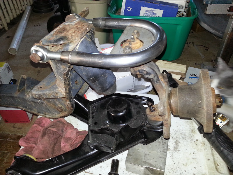
From a design standpoint, I think mine will be a little different, mainly because I plan to utilize the plasma cutter to make most of the parts.The Dark Side of Will wrote: ↑Sat May 02, 2015 1:30 pm Spare parts mockup. The control arm is on top of the ball joint in order to clear the Street Dreams knuckle (not pictured) at full ball joint angle.
I hadn't noticed this before, but there's a droop limiting feature on the crossmember which interacts with the stock control arm.

"I am not what you so glibly call to be a civilized man. I have broken with society for reasons which I alone am able to appreciate. I am therefore not subject to it's stupid laws, and I ask you to never allude to them in my presence again."
-
The Dark Side of Will
- Peer Mediator
- Posts: 15626
- Joined: Wed Nov 24, 2004 11:13 pm
- Location: In the darkness, where fear and knowing are one
- Contact:
Re: custom chassis/suspension considerations.
Adding caster vs your current setup is good, but it just gets you back to stock. Adding caster much above (or below) stock settings moves the outer tie rod end vertically out of place an creates bump steer. Steven Snyder is running something like 12 degrees on his '88, via his adjustable control arm and says bump steer is significant.ericjon262 wrote: ↑Thu Apr 07, 2022 4:50 pm 1. add additional caster to the front suspension. I should quantify this before continuing too much further.
Pothole and curb impacts are more severe load cases than a smooth track on slicks.ericjon262 wrote: ↑Thu Apr 07, 2022 4:50 pm 3. be strong enough to handle both everyday driving, and track abuse.
C5 wheel bearings have 30 splines. I don't think anything else GM built used that size. C6 ZO6 and all C7 hubs used 33 spline outer CV joints, which are common to the large FWD platforms. The 2nd gen W-body and C7 drive hubs are dimensionally interchangeable except for the wheel bolt pattern, for example.
I've checked some dimensions on Jeep cartridges and the ones I've looked at are bigger than the GM large pattern cartridge.
And yet... the parking brake shoes on my Benz are worn out
I selected my parking brake components based on fitting the parking brake inside a 8x7.62" rotor bolt circle. This bolt circle is used on some <$100 12.2x1.25" Wilwood rotors.ericjon262 wrote: ↑Thu Apr 07, 2022 4:50 pm I haven't put much effort into defining possibilities for rotors and calipers yet, Overall, I would like to stay 12"+ diameter, and I would prefer a 4 piston rigid mounted caliper, I would like to put effort into finding lightweight calipers and rotors, quick change pads would be a nice plus, but not required.
If you're not going to use those rotors or that RBC, then there's not a strong case for my parking brake design and you're probable better off sticking with the production GM (used on Caddies as well) parts.
I have CMM dimensions on an '88 front knuckle & 84-87 rear in OnShape. I shared them with Steven Snyder. I was going to do the same with an '84-'87 spindle as soon as I decided it was time to buy brand new ball joints and tie rod end to cut up.ericjon262 wrote: ↑Thu Apr 07, 2022 4:50 pm step 1 should be to gain dimensions of factory 84-87 UCA's, 84-87 spindles, and 88 rear knuckles.
If building a spindle/knuckle for the early car, dramatically reducing the scrub radius and using longer control arms would be a significant improvement in the front suspension.
Getting meaningful results from doing your own structural qualification is difficult.ericjon262 wrote: ↑Thu Apr 07, 2022 4:50 pm
step 3 will be model and prototype, and maybe destructive testing depending on the difficulty of the assembly and fixturing for testing.
step 4, will be a final "production" model, although, I'm not planning an actual production run at this point.
this is just a rough sheet of starting ideas, once I start working on more formal sketches, I'll post them. if you have any ideas i should be considering, I'm open to ideas.
FYI, willwood has nice parts drawings on their website, I'll probably be utilizing some of them. I know McMaster does as well, any other good ones that could be useful for this kind of undertaking? I don't expect this to be fast paced, I have alot on my plate, but it is a project that has been on my mind for a while.
FEA is becoming easier every day. For either test or analysis, the design loads are the key, but also the hard part to come up with accurately.
-
The Dark Side of Will
- Peer Mediator
- Posts: 15626
- Joined: Wed Nov 24, 2004 11:13 pm
- Location: In the darkness, where fear and knowing are one
- Contact:
Re: custom chassis/suspension considerations.
The parking brakes are handed, as the expander blocks are assembled in the opposite direction on each side. I made those two bolt holes slots in order to mount either brake to either knuckle and have flexibility in setting up the p-brake cable either '84-'87 or '88 style.ericjon262 wrote: ↑Thu Apr 07, 2022 9:02 pm this is a rough sketch of the C5 wheel bearing and parking brake mounting patterns, the parking brake mounts won't be needed for the front, so I should be able to omit them, pro tip, those are not the same distance from the axle/hub centerline
Neither of those attempts made it past experiment to prototype status.ericjon262 wrote: ↑Thu Apr 07, 2022 9:02 pm I have one main idea floating in my head for the control arm, rod ends on the chassis side provide camber adjustment, and the balljoint offset to the rear. I have an idea that would potentially allow for some adjustment of caster angle via rotating the ball joint mounts through an arc, this requires the ball join be able to move through a higher degree of motion than the stock Fiero joint, I'm not sure that amount of adjustment would really be beneficial though, I think the more important part will be getting both sides equal. the design is in my head, from a function standpoint, is similar to the horseshoe shaped UCA that Will built on "The Mule" here:
https://www.realfierotech.com/viewtopic ... 46#p151246
Not only would neither one have had enough droop travel, and would have required me to cut the droop stops off the crossmember, the also did not mimic the stock control arm's kingpin and anti-dive (caster) angles, which would have put the ball joint out of it's design range of motion.
Also, the '84-'87 rear ball joint and the '88 upper ball joint have the same bolt pattern in the control arm. There's no reason you couldn't use the '84-'87 *REAR* lower (or the bolt-in-compatible minivan ball joint with larger shank) for the upper ball joint. That would simplify the upper ball joint boss by not requiring a tapered reamer. The UBJ and LBJ tapers on an '88 knuckle are different. I have not had the tapers on an '84-'87 knuckle or the '88 tie rod end measured yet.
-
ericjon262
- Posts: 2824
- Joined: Mon May 24, 2010 5:34 pm
- Location: Aiken, SC
Re: custom chassis/suspension considerations.
There's currently quite a bit of bumpsteer, I haven't measured caster yet as is, I was thinking about shooting for 7-8 degrees. I think stock is 5,The Dark Side of Will wrote: ↑Fri Apr 08, 2022 8:13 pmAdding caster vs your current setup is good, but it just gets you back to stock. Adding caster much above (or below) stock settings moves the outer tie rod end vertically out of place an creates bump steer. Steven Snyder is running something like 12 degrees on his '88, via his adjustable control arm and says bump steer is significant.ericjon262 wrote: ↑Thu Apr 07, 2022 4:50 pm 1. add additional caster to the front suspension. I should quantify this before continuing too much further.
I agree.The Dark Side of Will wrote: ↑Fri Apr 08, 2022 8:13 pmPothole and curb impacts are more severe load cases than a smooth track on slicks.ericjon262 wrote: ↑Thu Apr 07, 2022 4:50 pm 3. be strong enough to handle both everyday driving, and track abuse.
Good info, thank you!The Dark Side of Will wrote: ↑Fri Apr 08, 2022 8:13 pmC5 wheel bearings have 30 splines. I don't think anything else GM built used that size. C6 ZO6 and all C7 hubs used 33 spline outer CV joints, which are common to the large FWD platforms. The 2nd gen W-body and C7 drive hubs are interchangeable except for the wheel bolt pattern, for example.
I've checked some dimensions on Jeep cartridges and the ones I've looked at are bigger than the GM large pattern cartridge.
yeah, from a wear standpoint, the wear is much slower than say, pads or rotors, when properly adjusted, and as much as I want a functional parking break, 1st or reverse will hold the car in place without it, so even if it does wear out, I can still hold the car in place by alternative means.The Dark Side of Will wrote: ↑Fri Apr 08, 2022 8:13 pmAnd yet... the parking brake shoes on my Benz are worn out
Right, it really depends on the availability of the rotors, if I go with a bolt pattern that limits me to 3 rotor options, that's less than ideal, I'll need to look at which circles offer the greatest availability and go from there.The Dark Side of Will wrote: ↑Fri Apr 08, 2022 8:13 pmI selected my parking brake components based on fitting the parking brake inside a 8x7.62" rotor bolt circle. This bolt circle is used on some <$100 12.2x1.25" Wilwood rotors.ericjon262 wrote: ↑Thu Apr 07, 2022 4:50 pm I haven't put much effort into defining possibilities for rotors and calipers yet, Overall, I would like to stay 12"+ diameter, and I would prefer a 4 piston rigid mounted caliper, I would like to put effort into finding lightweight calipers and rotors, quick change pads would be a nice plus, but not required.
If you're not going to use those rotors or that RBC, then there's not a strong case for my parking brake design and you're probable better off sticking with the production GM (used on Caddies as well) parts.
tomorrow, after work, I'm going to pick up a complete front suspension which I will use to get accurate dimensions of the spindles, I might beat you too the dimensions, I'm more than happy to share what I come up with.The Dark Side of Will wrote: ↑Fri Apr 08, 2022 8:13 pmI have CMM dimensions on an '88 front knuckle & 84-87 rear in OnShape. I shared them with Steven Snyder. I was going to do the same with an '84-'87 spindle as soon as I decided it was time to buy brand new ball joints and tie rod end to cut up.ericjon262 wrote: ↑Thu Apr 07, 2022 4:50 pm step 1 should be to gain dimensions of factory 84-87 UCA's, 84-87 spindles, and 88 rear knuckles.
If building a spindle/knuckle for the early car, dramatically reducing the scrub radius and using longer control arms would be a significant improvement in the front suspension.
I'm not sure if onshape has FEA available, it would be pretty cool to mess with if it does.The Dark Side of Will wrote: ↑Fri Apr 08, 2022 8:13 pmGetting meaningful results from doing your own structural qualification is difficult.ericjon262 wrote: ↑Thu Apr 07, 2022 4:50 pm
step 3 will be model and prototype, and maybe destructive testing depending on the difficulty of the assembly and fixturing for testing.
step 4, will be a final "production" model, although, I'm not planning an actual production run at this point.
this is just a rough sheet of starting ideas, once I start working on more formal sketches, I'll post them. if you have any ideas i should be considering, I'm open to ideas.
FYI, willwood has nice parts drawings on their website, I'll probably be utilizing some of them. I know McMaster does as well, any other good ones that could be useful for this kind of undertaking? I don't expect this to be fast paced, I have alot on my plate, but it is a project that has been on my mind for a while.
FEA is becoming easier every day. For either test or analysis, the design loads are the key, but also the hard part to come up with accurately.
More good info. for the sake of this part, I could cut one shape twice and attach parts to opposing sides.The Dark Side of Will wrote: ↑Fri Apr 08, 2022 8:28 pmThe parking brakes are handed, as the expander blocks are assembled in the opposite direction on each side. I made those two bolt holes slots in order to mount either brake to either knuckle and have flexibility in setting up the p-brake cable either '84-'87 or '88 style.ericjon262 wrote: ↑Thu Apr 07, 2022 9:02 pm this is a rough sketch of the C5 wheel bearing and parking brake mounting patterns, the parking brake mounts won't be needed for the front, so I should be able to omit them, pro tip, those are not the same distance from the axle/hub centerline
thanks for the ball joint tip, it's definitely something to consider. I wasn't aware of those issues you ran into, some of them would be fixable in the idea I had, but the droop limiter would not without some changes.The Dark Side of Will wrote: ↑Fri Apr 08, 2022 8:28 pmNeither of those attempts made it past experiment to prototype status.ericjon262 wrote: ↑Thu Apr 07, 2022 9:02 pm I have one main idea floating in my head for the control arm, rod ends on the chassis side provide camber adjustment, and the balljoint offset to the rear. I have an idea that would potentially allow for some adjustment of caster angle via rotating the ball joint mounts through an arc, this requires the ball join be able to move through a higher degree of motion than the stock Fiero joint, I'm not sure that amount of adjustment would really be beneficial though, I think the more important part will be getting both sides equal. the design is in my head, from a function standpoint, is similar to the horseshoe shaped UCA that Will built on "The Mule" here:
https://www.realfierotech.com/viewtopic ... 46#p151246
Not only would neither one have had enough droop travel, and would have required me to cut the droop stops off the crossmember, the also did not mimic the stock control arm's kingpin and anti-dive (caster) angles, which would have put the ball joint out of it's design range of motion.
Also, the '84-'87 rear ball joint and the '88 upper ball joint have the same bolt pattern in the control arm. There's no reason you couldn't use the '84-'87 lower (or the bolt-in-compatible minivan ball joint with larger shank) for the upper ball joint. That would simplify the upper ball joint boss by not requiring a tapered reamer. The UBJ and LBJ tapers on an '88 knuckle are different. I have not had the tapers on an '84-'87 knuckle or the '88 tie rod end measured yet.
====================================================================================================
Wilwood emailed me back, they had the most polite way of saying "fuck off, we want no part in this"
"I am not what you so glibly call to be a civilized man. I have broken with society for reasons which I alone am able to appreciate. I am therefore not subject to it's stupid laws, and I ask you to never allude to them in my presence again."
-
pmbrunelle
- Posts: 610
- Joined: Thu May 20, 2010 10:07 pm
- Location: Grand-Mère, QC
Re: custom chassis/suspension considerations.
So the tire generates Mz and Fy.ericjon262 wrote: ↑Thu Apr 07, 2022 4:50 pm 1. add additional caster to the front suspension. I should quantify this before continuing too much further.
In one school of thought, Fy is a most useful piece of info that should be communicated to the driver.
The more mechanical trail you have, the more you feel Fy in the steering wheel. Mz is transmitted just the same to the steering wheel, but percentage-wise, the steering wheel torque comes less from Mz as mechanical trail is increased. There is a limit because you want the steering wheel torque to remain easy enough.
With caster, you gain a bunch of camber as you crank over the steering wheel in low-speed turns.
There's also the idea of getting your mechanical trail by offsetting the steering axis ahead of the wheel bearing.
For some amount of mechanical trail, how much of that should be obtained via caster versus steering axis offset?
My dad keeps telling me that I should use my work email for stuff like this... some shops might get a hard-on thinking they'll be selling thousands of something per year by talking to me.ericjon262 wrote: ↑Sat Apr 09, 2022 9:03 pm Wilwood emailed me back, they had the most polite way of saying "fuck off, we want no part in this"
Bridgestone is a pretty big name in automotive
I talked a bit about that here:The Dark Side of Will wrote: ↑Fri Apr 08, 2022 8:13 pm For either test or analysis, the design loads are the key, but also the hard part to come up with accurately.
https://www.fiero.com/forum/Forum2/HTML/ ... 2.html#p74
-
The Dark Side of Will
- Peer Mediator
- Posts: 15626
- Joined: Wed Nov 24, 2004 11:13 pm
- Location: In the darkness, where fear and knowing are one
- Contact:
Re: custom chassis/suspension considerations.
The contact patch generates Fy via "slip". The tread blocks touch the pavement at the front edge of the contact patch, then get stretched to the side as the tire rolls until the tread block is no longer in contact with the pavement. The rubber at the back edge of the contact patch is stretched more and generates more Fy than the rubber at the front edge of the contact patch. While the tire is experiencing slip, the center of force of the contact patch is aft of the geometric center of the contact patch.pmbrunelle wrote: ↑Sun Apr 10, 2022 1:22 amSo the tire generates Mz and Fy.ericjon262 wrote: ↑Thu Apr 07, 2022 4:50 pm 1. add additional caster to the front suspension. I should quantify this before continuing too much further.
In one school of thought, Fy is a most useful piece of info that should be communicated to the driver.
The more mechanical trail you have, the more you feel Fy in the steering wheel. Mz is transmitted just the same to the steering wheel, but percentage-wise, the steering wheel torque comes less from Mz as mechanical trail is increased. There is a limit because you want the steering wheel torque to remain easy enough.
With caster, you gain a bunch of camber as you crank over the steering wheel in low-speed turns.
There's also the idea of getting your mechanical trail by offsetting the steering axis ahead of the wheel bearing.
For some amount of mechanical trail, how much of that should be obtained via caster versus steering axis offset?
As the rubber at the back edge of the contact patch gets stretched so far that it starts to slide across the pavement, the tire is at maximum slip. Push it harder and the zone of the contact patch that has transitioned from slip to sliding expands toward the front of the contact patch. When the entire contact patch is sliding, the center of force of the contact patch is at the geometric center of the contact patch.
The movement of the center of force reduces mechanical trail, thereby reducing steering wheel torque. This change is what the steering has to communicate to the driver in order to allow the driver to get everything possible out of the front tires. With "too much" mechanical trail, the percentage of steering torque reduction from the contact patch transitioning from slip to slide is "too small" and the driver does not have good sensitivity to how he's using the contact patch.
I'm interested in playing with offsetting the wheel centerline forward of the steering axis (I *think* this is Forlauf) in order to keep a large caster angle for stability and caster-induced camber gain, while keeping mechanical trail low enough to retain good contact patch feel.
-
The Dark Side of Will
- Peer Mediator
- Posts: 15626
- Joined: Wed Nov 24, 2004 11:13 pm
- Location: In the darkness, where fear and knowing are one
- Contact:
Re: custom chassis/suspension considerations.
Link needs fixing?pmbrunelle wrote: ↑Sun Apr 10, 2022 1:22 am I talked a bit about that here:
https://www.fiero.com/forum/Forum2/HTML ... 2.html#p74
-
pmbrunelle
- Posts: 610
- Joined: Thu May 20, 2010 10:07 pm
- Location: Grand-Mère, QC
Re: custom chassis/suspension considerations.
The Dark Side of Will wrote: ↑Sun Apr 10, 2022 8:05 am The rubber at the back edge of the contact patch is stretched more and generates more Fy than the rubber at the front edge of the contact patch. While the tire is experiencing slip, the center of force of the contact patch is aft of the geometric center of the contact patch.
As you have implicitly stated, peak Mz happens at a lesser slip angle than peak Fy.The Dark Side of Will wrote: ↑Sun Apr 10, 2022 8:05 am Push it harder and the zone of the contact patch that has transitioned from slip to sliding expands toward the front of the contact patch. When the entire contact patch is sliding, the center of force of the contact patch is at the geometric center of the contact patch.
So... according to the view I mentioned, some drivers may interpret the initial drop in steering wheel torque (after passing the Mz peak) as the limit of the car, so they don't take corners any faster. However, there's really more Fy to be had with more slip angle, but drivers don't go there because they felt the steering lighten up already. Driver experience would be a factor here.
I'm not sure what cues to the driver make a man+machine combo fast. Human drivers can adapt to different kinds of cars.
The interwebz say Vorlauf.The Dark Side of Will wrote: ↑Sun Apr 10, 2022 8:05 am I'm interested in playing with offsetting the wheel centerline forward of the steering axis (I *think* this is Forlauf) in order to keep a large caster angle for stability and caster-induced camber gain, while keeping mechanical trail low enough to retain good contact patch feel.
That's an interesting idea.
Do you think you want to try different amounts of offset?
I removed the "s" from the https:The Dark Side of Will wrote: ↑Sun Apr 10, 2022 8:06 amLink needs fixing?pmbrunelle wrote: ↑Sun Apr 10, 2022 1:22 am I talked a bit about that here:
https://www.fiero.com/forum/Forum2/HTML ... 2.html#p74
http://www.fiero.com/forum/Forum2/HTML/ ... 2.html#p74
-
ericjon262
- Posts: 2824
- Joined: Mon May 24, 2010 5:34 pm
- Location: Aiken, SC
Re: custom chassis/suspension considerations.
using my work email is a great idea, for some reason Wilwood emailed me again(I didn't respond to their original email), with the same info, I responded with a more clear description of the what I am doing, maybe that will obtain the desired results without masking my questions in a work email? not super worried about it either way.
my original plan here, was new spindles, and new UCA's, further thought had me realize that it starts to look quite silly spending all of this effort on maintaining any stock parameters, when I'll be making the hardest parts to make of the whole assembly. I have a factory front suspension in the garage that I can use to take measurements off of, at least for the crossmember mounting points. I am now considering just making a new crossmember that bolts in place of the stock one, but carries all of the front suspension mounting points, more like an 88 front. the stock crossmember has brace points to the front of the car, and a lateral brace is mounted behind the crossmember that could be used to brace it to the rear so the LCA loads are transmitted to the body instead of trying to rip the bolts out of the front frame, although I'm not sure that much bracing would even be required. further thought had me wondering if I should look towards a stock spindle like the C5 parts, as they are lighter, supported in the aftermarket, and plenty strong/proven for my needs.
reading on scrub radius makes me think I need to make wheel choices earlier on in this game, as changes in offsets will change SR. due to the wheel bearing change, I will have to change wheels, I don't plan on changing tire sizes though.
offsetting the wheel bearing to the steering axis is a new one for me, I don't think I have ever seen that implemented, and I wonder what that feels like in the car. googling it didn't seem to give many results. so far, I have only found one vehicle to do that(5th generation Toyota Celica https://global.toyota/en/detail/7825966 ) with no data provided as to how much offset was applied.
this discussion has quickly refreshed to me that I need to learn more about suspension dynamics and geometry, I have a couple of books somewhere around here that I need to dig out and read again/more thoroughly.
"I am not what you so glibly call to be a civilized man. I have broken with society for reasons which I alone am able to appreciate. I am therefore not subject to it's stupid laws, and I ask you to never allude to them in my presence again."
-
The Dark Side of Will
- Peer Mediator
- Posts: 15626
- Joined: Wed Nov 24, 2004 11:13 pm
- Location: In the darkness, where fear and knowing are one
- Contact:
Re: custom chassis/suspension considerations.
Remember that any discussion of handling that does not begin and end with tires is a waste?ericjon262 wrote: ↑Tue Apr 12, 2022 6:53 am reading on scrub radius makes me think I need to make wheel choices earlier on in this game, as changes in offsets will change SR. due to the wheel bearing change, I will have to change wheels, I don't plan on changing tire sizes though.
Start with tires, spec the wheels, select all your hub & brake components... then you know the space in which you can put ball joints.
Yeah, I've heard of Vorlauf/Nachlauf, but it's not discussed much when implemented... or maybe is implemented on tractors instead of carsericjon262 wrote: ↑Tue Apr 12, 2022 6:53 am offsetting the wheel bearing to the steering axis is a new one for me, I don't think I have ever seen that implemented, and I wonder what that feels like in the car. googling it didn't seem to give many results. so far, I have only found one vehicle to do that(5th generation Toyota Celica https://global.toyota/en/detail/7825966 ) with no data provided as to how much offset was applied.
this discussion has quickly refreshed to me that I need to learn more about suspension dynamics and geometry, I have a couple of books somewhere around here that I need to dig out and read again/more thoroughly.
-
ericjon262
- Posts: 2824
- Joined: Mon May 24, 2010 5:34 pm
- Location: Aiken, SC
Re: custom chassis/suspension considerations.
Right, I wasn't planning on changing the tire size but wheels will ahv to change based on the hub patterns available, which means offsets could changes which then changed scrub radius.
I don't think I've ever seen a tractor without front/rear solid axles, I also don't think I have ever seen one where much effort was put into suspension geometry... Lol!
I don't think I've ever seen a tractor without front/rear solid axles, I also don't think I have ever seen one where much effort was put into suspension geometry... Lol!
"I am not what you so glibly call to be a civilized man. I have broken with society for reasons which I alone am able to appreciate. I am therefore not subject to it's stupid laws, and I ask you to never allude to them in my presence again."
-
pmbrunelle
- Posts: 610
- Joined: Thu May 20, 2010 10:07 pm
- Location: Grand-Mère, QC
Re: custom chassis/suspension considerations.
The Dark Side of Will wrote: ↑Tue Apr 12, 2022 9:39 am Yeah, I've heard of Vorlauf/Nachlauf, but it's not discussed much when implemented... or maybe is implemented on tractors instead of cars
Tractors do occasionally need to be driven on roads between different fields.ericjon262 wrote: ↑Tue Apr 12, 2022 10:25 am I don't think I've ever seen a tractor without front/rear solid axles, I also don't think I have ever seen one where much effort was put into suspension geometry... Lol!
There is/was some interest from agricultural OEMs to improve the driveability/safety of their vehicles while driving on the road.
A few years ago at my work, we did some exploratory work with OEMs to add steering feel to agricultural vehicles normally having a zero-feel hydraulic orbitrol steering valve. Nothing progressed beyond the RFQ/prototyping stage though.
When you make synthetic/semi-synthetic steering feel, the actual mechanical linkage setup matters less.
Instead, what you do (in software) is:
Estimate what the tire is doing
Invent a fictitious steering linkage having the feel you desire
Feed the calculated forces from the tire into the fictitious steering linkage
Send torque feedback to the driver based on the torque appearing at the steering wheel of the fictitious linkage.
An obvious challenge with agriculture is that the tire can run on many different surfaces, so different tire models are needed, and you need to switch models depending on which surface you're running on. Quality of feel can depend on the type/number of sensors used to feed into the tire model, with tie-rod sensors obviously being useful.
"Self-centering" was an often-stated goal of these projects, so people naturally wanted to implement a "spring" function. Torque proportional to steering angle.
A major challenge of these projects was to convince managers that a spring did not constitute helpful steering feedback, and in fact constituted noise the driver didn't need... Helpful steering feedback, in my view, meant something relating to what the tires are doing... but ya know, that would require more man-hours, more $$$.
-
The Dark Side of Will
- Peer Mediator
- Posts: 15626
- Joined: Wed Nov 24, 2004 11:13 pm
- Location: In the darkness, where fear and knowing are one
- Contact:
Re: custom chassis/suspension considerations.
The self-centering and contact patch feel are different magnitudes, though.
In flight school, we had to listen to both VHF (civilian air traffic) and UHF (military air traffic) radios while flying. To do that and catch the traffic, we would turn the volume up on the UHF and down on the VHF, so that we could tell which radio was making noise by the volume. After doing this for a while, we could even listen to two people talking at the same time and catch most of what was said. The lack of variety in air traffic radio transmissions helps a lot, of course.
Point being that if the magnitudes of the forces are different, then the driver can sort them out without self-centering becoming noise.
Cars get contact patch feel from mechanical trail and self centering from kingpin inclination and caster... balancing these forces so that self-centering is low enough force--or contact patch feel is high enough force--that they don't interfere with each other should totally be fun.
-
ericjon262
- Posts: 2824
- Joined: Mon May 24, 2010 5:34 pm
- Location: Aiken, SC
Re: custom chassis/suspension considerations.
right, artificial road feel and artificial self centering aren't exactly a goal, I would suspect the level of engineering that would go into that would be a bit above what I want to do, as well as I suspect getting it right would lead to thousands of hours of tuning just to have a fairly unpredictable system.
I dug out a copy of "Tires, Suspension and Handling" that I've been kicking around for a while, it's written like a textbook, but appears to have a ton of good information. I'm going to read over it a bit, and start taking a few stabs at a viable design.
I dug out a copy of "Tires, Suspension and Handling" that I've been kicking around for a while, it's written like a textbook, but appears to have a ton of good information. I'm going to read over it a bit, and start taking a few stabs at a viable design.
"I am not what you so glibly call to be a civilized man. I have broken with society for reasons which I alone am able to appreciate. I am therefore not subject to it's stupid laws, and I ask you to never allude to them in my presence again."
-
The Dark Side of Will
- Peer Mediator
- Posts: 15626
- Joined: Wed Nov 24, 2004 11:13 pm
- Location: In the darkness, where fear and knowing are one
- Contact:
Re: custom chassis/suspension considerations.
LOL! We know why parking brake shoes wear out and it has nothing to do with proper use...ericjon262 wrote: ↑Sat Apr 09, 2022 9:03 pmyeah, from a wear standpoint, the wear is much slower than say, pads or rotors, when properly adjusted, and as much as I want a functional parking break, 1st or reverse will hold the car in place without it, so even if it does wear out, I can still hold the car in place by alternative means.The Dark Side of Will wrote: ↑Fri Apr 08, 2022 8:13 pmAnd yet... the parking brake shoes on my Benz are worn out
-
ericjon262
- Posts: 2824
- Joined: Mon May 24, 2010 5:34 pm
- Location: Aiken, SC
Re: custom chassis/suspension considerations.
right, on a Fiero, that means driving around with it left on, if you can yank the parking brake and reset it while driving a 5 speed, you're braver than me, or you have more than 2 arms.The Dark Side of Will wrote: ↑Thu Apr 14, 2022 9:12 amLOL! We know why parking brake shoes wear out and it has nothing to do with proper use...ericjon262 wrote: ↑Sat Apr 09, 2022 9:03 pmyeah, from a wear standpoint, the wear is much slower than say, pads or rotors, when properly adjusted, and as much as I want a functional parking break, 1st or reverse will hold the car in place without it, so even if it does wear out, I can still hold the car in place by alternative means.The Dark Side of Will wrote: ↑Fri Apr 08, 2022 8:13 pmAnd yet... the parking brake shoes on my Benz are worn out
"I am not what you so glibly call to be a civilized man. I have broken with society for reasons which I alone am able to appreciate. I am therefore not subject to it's stupid laws, and I ask you to never allude to them in my presence again."
-
The Dark Side of Will
- Peer Mediator
- Posts: 15626
- Joined: Wed Nov 24, 2004 11:13 pm
- Location: In the darkness, where fear and knowing are one
- Contact:
Re: custom chassis/suspension considerations.
Happens more often than you might think 
Especially when the brake is only marginally effective.
What blows my mind is that in the Benz if you move the car with the brake on, you get an aggressive chime and an angry red warning in the dash... and yet my parking brake shoes are still worn out.
Especially when the brake is only marginally effective.
What blows my mind is that in the Benz if you move the car with the brake on, you get an aggressive chime and an angry red warning in the dash... and yet my parking brake shoes are still worn out.