The Mule rides again (sort of) - pics.

Real tech discussion on design, fabrication, testing, development of custom or adapted parts for Pontiac Fieros. Not questions about the power a CAI will give.

Moderators: The Dark Side of Will, Series8217

The Dark Side of Will
Peer Mediator
Posts: 15629
Joined: Wed Nov 24, 2004 11:13 pm
Location: In the darkness, where fear and knowing are one
Contact:

Re: The Mule rides again (sort of) - pics.

Post by The Dark Side of Will »

I have these at all four corners of my powertrain: http://pitstopusa.com/i-5073747-prothan ... QgodnysA4A

Image

BUT they are all down on the cradle. I don't have any top-side mounts.

The powertrain is VERY firm, but also VERY springy... I can tell by the way it surges at parking lot speeds that the mounts are winding up with a good bit of energy.

Because those mounts are fairly close to the axle centerline, they see a good bit of force from axle torque. (~315 ftlbs at the flywheel ~ 4000 ftlbs at the axle in first gear)

A top side mount would be further from the axle centerline, see less force and be better able to constrain the motion of the powertrain.

Your car's an '88, right, Shaun?
User avatar
Shaun41178(2)
Posts: 8464
Joined: Fri Nov 19, 2004 7:12 pm
Location: Ben Phelps is an alleged scammer

Re: The Mule rides again (sort of) - pics.

Post by Shaun41178(2) »

Yes
User avatar
Series8217
1988 Fiero Track Car
Posts: 5989
Joined: Thu Jun 02, 2005 9:47 pm
Location: Los Angeles, CA

Re: The Mule rides again (sort of) - pics.

Post by Series8217 »

The Dark Side of Will wrote: The hinge pin on my left decklid hinge broke weekend before last... I'll be rebuilding it this weekend. I could go for a drive with the decklid off and a helper installed in the passenger seat to watch the engine as I abuse the car.
I learned a lot by taking off my decklid and sticking a GoPro to the rear window with a suction cup mount. A lot of sport cams and modern point-and-shoot cameras have enough resolution to capture some good footage, and most offer high-speed framerates (60fps+) too, which can be useful for capturing oscillations.
User avatar
Series8217
1988 Fiero Track Car
Posts: 5989
Joined: Thu Jun 02, 2005 9:47 pm
Location: Los Angeles, CA

Re: The Mule rides again (sort of) - pics.

Post by Series8217 »

Series8217 wrote:I was able to look through my parts in the barn and didn't find it there. There's still a chance I have one in the garage, but access to my parts was blocked and we didn't have time to move the lift and other stuff out of the way. I will make a more concerted effort on getting back there when I'm up there in 3 weeks.
Sorry Will, couldn't find it.
The Dark Side of Will
Peer Mediator
Posts: 15629
Joined: Wed Nov 24, 2004 11:13 pm
Location: In the darkness, where fear and knowing are one
Contact:

Re: The Mule rides again (sort of) - pics.

Post by The Dark Side of Will »

D-oh! Thanks for looking.

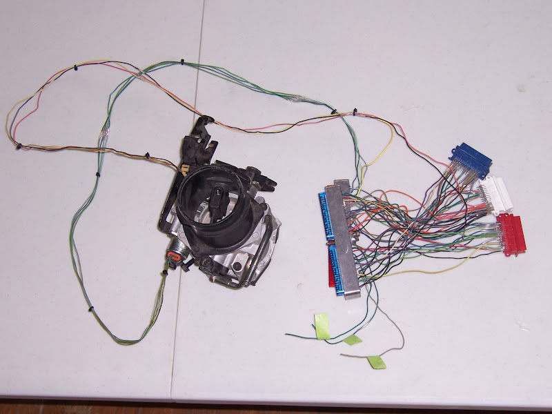
I was able to take a few hours yesterday and today to do the majority of the work on the wiring harness adapter for the Shelby PCM.

I'll come back and fix these photos:
Edit: Fixed.
The Dark Side of Will wrote:
In order to minimize the number of changes at once, I'm going to build a harness adapter in order to use the Shelby computer with my current harness. All of the following parts will have to be added to it.
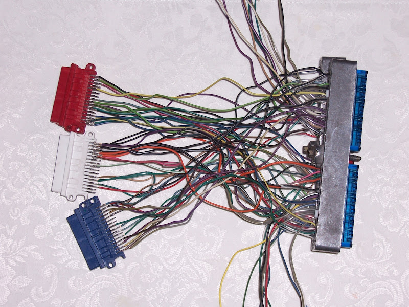
Altrbo was nice enough to put his mad JDM tyte j0 NASA skillz to work and rip the connectors off a '90's Buick PCM for me. These are the same connectors used by the OBDI Caddy PCM. Sinister was able to get me a pigtail with the Shelby computer. I'll marry these up to the pigtail to make the adapter.

Image

Image

Image

This is a MAF sensor connector. That should be fairly straight forward. I believe these are available through CarQuest. I'll just have to run an independent pigtail to it from the ECM harness adapter which will be inside the car with the ECM.

Image

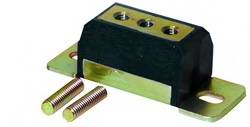
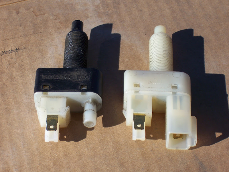
This is the IAC connector. That one in and of itself won't be a problem either. However, it will need to be part of a second smaller harness adapter which will adapt the ISM wiring for the '93-'95 throttle body I currently have to the IAC connector on the '96+ throttle body I'm going to use. The ISM uses what is essentially a 4 pin weatherpak, BUT the connector position assurance (CPA) clip is at one end of the connector for the ISM, while it's in the middle for the standard 4 pin weatherpack.

Image

Once the Shelby computer is installed, tuned and has some trouble-free miles on it, I'll completely rework the harness into Northstar-Fiero Harness v. 2.0. That will change the routing to keep more wiring out of sight and possibly more the ECM to the engine bay or into the wheel house behind the quarter panel.
Edit:
The MAF connector shown above is from my dad's 400 SBC Jaguar running LT1 controls and 3 wire MAF with separate IAT. The Caddy MAF that's integrated to the OBDII throttle body has an integral IAT and therefore a 5 wire connector.
The IAC connector shown above is the one I'll need, however.

Image

Remaining to be done:
-Populate a 3 or more pin Molex which carries a clutch switch wire, and +12V/GND for the MAF sensor from the interior body harness. Theoretically, I could have brought them off the backs of the adapter connectors, but space is at a premium when soldering to those pins, and the existing power/ground wires are 18 ga rather than 22. There just wasn't space to get everything in and allow room for the shrink tube which will be needed to assure isolation.
-Build an additional pigtail for the MAF and connect it to the aforementioned Molex as well as the signal pin on the Shelby connectors.
-Provide for a connection to the IAC, either by building an adapter to go from the ISM to the IAC or by running a dedicated pigtail similar to that which I will have to build for the MAF sensor. The ISM to IAC adapter is complicated by the fact that one of the ISM wires goes directly to ground, so I have to run one wire the entire length ANYWAY... might as well run three more and have one less connector to worry about.
-Obtain and wire in an OBDII DLC.

Once I do those things, the car will be ready for swapping the throttle to an OBDII unit and trying the Shelby PCM.

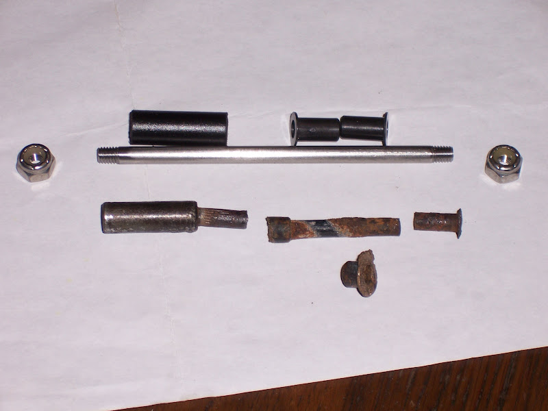
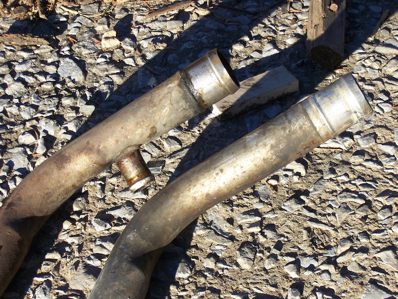
Also, the left decklid hinge pin broke, so I had to develop a replacement:

Image
The Dark Side of Will
Peer Mediator
Posts: 15629
Joined: Wed Nov 24, 2004 11:13 pm
Location: In the darkness, where fear and knowing are one
Contact:

Re: The Mule rides again (sort of) - pics.

Post by The Dark Side of Will »

The Dark Side of Will
Peer Mediator
Posts: 15629
Joined: Wed Nov 24, 2004 11:13 pm
Location: In the darkness, where fear and knowing are one
Contact:

Re: The Mule rides again (sort of) - pics.

Post by The Dark Side of Will »

I was an idiot and was going by the Shelby wiring diagrams instead of looking at the Caddy MAF sensor. The Caddy MAF sensor really is the 3 wire connector shown above. The Caddy has the IAT independent of the MAF.

I picked up the MAF and IAC connectors from a junk yard over the weekend. Unfortunately I didn't get them installed to the harness adapter because I couldn't find the right crimp tool for the butt splices because the cleaning lady had "cleaned" the room at my dad's house where I still have my wiring harness supplies. Grrrr....

I pulled the extraneous wires out of the Shelby PCM connectors, and only have the MAF signal, IAC quartet, clutch switch and two A/C wires left.

The Shelby A/C control is VERY similar to the Fiero's in that it has an A/C request line which tells the PCM that the driver has turned on the A/C, but it also has a pressure cycling switch input, which is wired to both the pressure cycling switch AND the high pressure cut-out switch. In the Fiero, the pressure cycling switch is in series with the HVAC panel on the A/C request line, and the high pressure cutout switch grounds the compressor clutch under normal circumstances.

I still need to look at the Fiero cruise control diagram, but I suspect that I can pirate the cruise clutch switch to do the task that the ECM needs.

I looked again, and I think I can pull +12V power for the MAF off the back of the harness connector after all.
User avatar
Series8217
1988 Fiero Track Car
Posts: 5989
Joined: Thu Jun 02, 2005 9:47 pm
Location: Los Angeles, CA

Re: The Mule rides again (sort of) - pics.

Post by Series8217 »

The Dark Side of Will wrote: Image

Edit: Looks like I need to do something about the heater inlet cap as well...
I noticed last night that mine looks like yours.

Found this today: http://www.ebay.com/itm/Samco-silicone- ... 00&vxp=mtr

Looks like Samco makes silicone bypass caps! No more cracking rubber every 4 years.
The Dark Side of Will
Peer Mediator
Posts: 15629
Joined: Wed Nov 24, 2004 11:13 pm
Location: In the darkness, where fear and knowing are one
Contact:

Re: The Mule rides again (sort of) - pics.

Post by The Dark Side of Will »

Sweeet product...

But I'll be solving the cap problem by replumbing the car to eliminate caps. The cap pictured above is the Caddy heater return connection on the engine. On the '87 & '88 cars, the heater return goes directly into the right side coolant pipe. I went with that and capped the connection on the engine. This means that I don't have heat until the thermostat opens.

A few months ago I snagged the heater pipes and right side coolant pipe from an '86 V6 in the junk yard. I'll be swapping in at least the coolant pipe soon. I'll run an extra hose to the heater return connection until I can transition to the Caddy heater pipes that wrap around the back of the engine.
The Dark Side of Will
Peer Mediator
Posts: 15629
Joined: Wed Nov 24, 2004 11:13 pm
Location: In the darkness, where fear and knowing are one
Contact:

Re: The Mule rides again (sort of) - pics.

Post by The Dark Side of Will »

Notes:
On a recommendation from this thread in SpeedTalk: http://speedtalk.com/forum/viewtopic.php?f=1&t=33125
I called these guys: http://crankshaftsupply.com/

They'll do nitriding for $167 and grinding/micropolishing for $107.
He said they grind to size and polish first, then send out for bath nitride (I do need to verify that's the right process for a *cast* vice forged or billet crank). Once it comes back from nitriding, it gets checked for straightness and has a final micropolish if necessary. The nitriding is .003-.005 deep.
Based on the input from that thread, I will also be going for 0.0015 main and 0.002 rod clearances on the new crank.

I'll probably send the crank out for cryo along with the 3.94 FD, differential side/spider gears (and maybe the whole diff carrier), spare left inner CV joint cup and intermediate shaft.

The driveline parts will then be WPC'd while the crank goes for nitriding.

I'm thinking that Liberty will be the service provider for the cryo treatment. http://www.libertysgears.com/metal%20enhancement.htm
I'm not sure if they do WPC or conventional polishing.
The Dark Side of Will
Peer Mediator
Posts: 15629
Joined: Wed Nov 24, 2004 11:13 pm
Location: In the darkness, where fear and knowing are one
Contact:

Re: The Mule rides again (sort of) - pics.

Post by The Dark Side of Will »

Did finally get the horrible RCC bump steer kit replaced with stock tie rods.

Image

I bought the inners from the FieroStore. They came with the 12x1.75 set screw, but no mounting nut. I used a 12x1.75x25 bolt and a couple of thick washers instead of a nut with the set screw used as a stud.

Image

The rear end is somewhat more stable, but I think I still have some looseness that I need to track down.
The Dark Side of Will
Peer Mediator
Posts: 15629
Joined: Wed Nov 24, 2004 11:13 pm
Location: In the darkness, where fear and knowing are one
Contact:

Re: The Mule rides again (sort of) - pics.

Post by The Dark Side of Will »

Finished the runs to the MAF and IAC... only have two A/C wires and clutch switch left to deal with.

Image
The Dark Side of Will
Peer Mediator
Posts: 15629
Joined: Wed Nov 24, 2004 11:13 pm
Location: In the darkness, where fear and knowing are one
Contact:

Re: The Mule rides again (sort of) - pics.

Post by The Dark Side of Will »

I'll be needing an OBDII datalogger to go through the update process with Ryan. Does anyone have any suggestions?

Here are a few I've found:
http://www.scantool.net/software/scanxl-pro.html

http://www.auterraweb.com/android-obdii.html

http://www.arctictools.com/diagnostic-t ... 4AodFksAeg

I don't need a fancy display or quick data transfer... My preference is actually for SIMPLE. My ideal device has a volume not greater than 3 cubic inches, has an OBDII connector and an SD card socket, and that's it. Anything beyond that is bells and whistles, but not much added functionality for what I want to do.
User avatar
Series8217
1988 Fiero Track Car
Posts: 5989
Joined: Thu Jun 02, 2005 9:47 pm
Location: Los Angeles, CA

Re: The Mule rides again (sort of) - pics.

Post by Series8217 »

I have a ScanTool 426101 OBDLink MX Bluetooth/OBD-II Scan Tool Interface and a Nexus 7 (Android Tablet) with the Torque Pro app. I'll try to generate some logs this week from the Apocalypse Wagon and upload them to my website so you can see how it does.
The Dark Side of Will
Peer Mediator
Posts: 15629
Joined: Wed Nov 24, 2004 11:13 pm
Location: In the darkness, where fear and knowing are one
Contact:

Re: The Mule rides again (sort of) - pics.

Post by The Dark Side of Will »

That looks like a very interesting device... and it's MUCH smaller than the comparable OBDII to bluetooth interface from Auterra
The Dark Side of Will
Peer Mediator
Posts: 15629
Joined: Wed Nov 24, 2004 11:13 pm
Location: In the darkness, where fear and knowing are one
Contact:

Re: The Mule rides again (sort of) - pics.

Post by The Dark Side of Will »

I have the clutch switch figured out.

The existing cruise clutch switch is not adaptible to this purpose. It is wired in series with the 2nd pole of the brake light switch to connect +12V to the cruise module. I don't want to rewire it because I want to install electro-cruise on this car eventually. The other "pole" of the stock switch is a vacuum valve that is not used on the Fiero. This is the cruise clutch switch:
http://www.ebay.com/itm/110936785155
(Delco terminology: "VALVE ASM-CRCONT VAC REL", "Speed control valve", P/N 212-347)

Image

The brake light switch has a normally open pole that closes the circuit to operate the rear brake lights and the CHMSL. It has a normally closed pole to operate the cruise control *module* clutch and brake input.

The "cruise brake switch" (FSM term) is a separate two-pole switch (the upper switch in the photo below). Both poles are normally closed and open when the pedal is depressed. The first (yellow/black wires) operates the vacuum dump solenoid on the cruise control *servo*, and the second (pink and purple wires) disengages the torque converter clutch. Photo of the cruise brake switch from Pfiffle:

Image

The cruise clutch switch and the cruise brake switch have the same diameter mounting. The clutch switch electrical pole and the brake switch TCC pole appear to be identical. The brake switch cruise servo pole would do *EXACTLY* what I need the clutch switch to do for the Shelby computer.
It *should* be as simple as swapping an extra brake switch into the clutch switch location.
Except that I can't find a part number for the brake switch.

Anyone know?

I'm pretty sure I have one or more of these in parts cars, so this is a temporary problem which I may be able to resolve this weekend... I'm just frustrated I can't find the listing.
Thanks!

Once I have the switch and connector, I can ground one side and run the other to the C203-A pin, and from there to the Caddy harness connectors and from there to the Shelby computer connectors.
The Dark Side of Will
Peer Mediator
Posts: 15629
Joined: Wed Nov 24, 2004 11:13 pm
Location: In the darkness, where fear and knowing are one
Contact:

Re: The Mule rides again (sort of) - pics.

Post by The Dark Side of Will »

Every now and then, Pfiffle is useful for something:

http://www.fiero.com/forum/Forum2/HTML/126747.html

Part I'm looking for is 10024217, but appears that current support is thin.
I did find a couple of sources, though:
http://www.gmpartsclub.com/oem-part/cad ... h/10024217
http://www.rarenosparts.com/84-88-GM-CR ... p_220.html
The Dark Side of Will
Peer Mediator
Posts: 15629
Joined: Wed Nov 24, 2004 11:13 pm
Location: In the darkness, where fear and knowing are one
Contact:

Re: The Mule rides again (sort of) - pics.

Post by The Dark Side of Will »

I spoke to Rocko at Liberty's Gears about having their range of metal enhancement processes done on my 3.94 gearset, the side and spider gears from my EPLSD and one or more CV joint cups and intermediate shafts. http://www.libertysgears.com/metal%20enhancement.htm

They cryo treat and then draw back to 56-59 rockwell for shafts/gears. They stay on the soft end for drag racing apps and can go to the harder end for road racing apps.

Cryo = $4/lb
Draw-back: $250 normal; potentially less for smaller

Thermal stabilization: $35/lot (a lot can be several parts)

Shot peen: $50/order

$16/small part for surface enhancement
$32 or $64 or larger parts
They charge $64/per barrel. A large part can take up an entire barrel, but one barrel can take multiple smaller parts.
Their process is similar to Mikronite. The first step uses dish soap & water + "pins" as the micro-peen media. The second step is either a walnut shell or corn cob polish. The process does not remove material or alter the profile of gear teeth.
The Dark Side of Will
Peer Mediator
Posts: 15629
Joined: Wed Nov 24, 2004 11:13 pm
Location: In the darkness, where fear and knowing are one
Contact:

Re: The Mule rides again (sort of) - pics.

Post by The Dark Side of Will »

Old switch (left) vs. new:

Image

The important difference between the '87 coolant pipe (left) and '86 coolant pipe:

Image

'87 heater pipes (top) vs. '86 heater pipes:

Image

And the real distinction between the two:

Image

I installed the '86 right coolant pipe in the car. I fastened the '86 heater pipes with the two small screws to the two bosses in the fuel tank tunnel, but didn't get to the heavier clamps at the ends yet. The forward ends of the pipes are the same, of course. The '87 hoses are nicer than the '86 hoses (1 piece vs. 2), so I kept the '87 parts.
The '87 supply has a quick-connect fitting and an elbow that fits between the right forward cradle mount ears. I had run a hose from the Northstar heater supply connection at the left rear corner of the engine bay around the engine bay counterclockwise and connected to this elbow at that location. The '87 return T's into the side of the coolant pipe.
The engine compartment ends are just about perfect for the Northstar... They come up just to the left of the alternator and allow me to run the heater hoses along the "shelf" at the bottom of the firewall panel. Both heater hoses will run along the shelf and circle around the left end of the engine bay to mate to the previously mentioned heater supply and the heater circuit return on the thermostat housing at the left front corner of the engine.

Once the original coolant circulation is restored, I'll have heat more quickly on cold mornings. The engine may even warm up more quickly also.
I have drill this coming weekend, so I won't be able to work on the car again until the 2nd. At that time, I'll finish replumbing the heater circuit and will replace the damaged coolant hose from the thermostat to the cross-cradle pipe. Some time soon, I'll also replace the cross-cradle pipe with one of these: http://www.partman.com/cooler-12-x-1-1- ... -quot.html or one of these: http://www.partman.com/cooler-ps-oil-16-1-2-quot.html

I also *FINALLY* have my anti-dive spacers machined, so I'll be able to install those soon.

I also drilled and tapped the splined ends of 3 CV joint cups and BOTH ends of my spare IMS with 10/32 holes for easy extraction of broken ends, when I break another axle. Those should go to Liberty this week along with the 3.94 FD and diff components.
The Dark Side of Will
Peer Mediator
Posts: 15629
Joined: Wed Nov 24, 2004 11:13 pm
Location: In the darkness, where fear and knowing are one
Contact:

Re: The Mule rides again (sort of) - pics.

Post by The Dark Side of Will »

Found a better price on the dual cooler: http://www.mrcool.us/85152t-mercruiser- ... ooler.html
Post Reply