The Mule rides again (sort of) - pics.
Moderators: The Dark Side of Will, Series8217
Re: The Mule rides again (sort of) - pics.
For the later OBD2 stuff that doesn't have an EGR, you can also use the A/C pressure input or the fuel tank pressure input. I am using the fuel tank pressure input in the E67 for my wideband, but it only logs the voltage. I dump the logs into excel spreadsheets so I have the conversion in the spreadsheets (along with filters for transient states, negative engine torque and clutch pushed in).
-
The Dark Side of Will
- Peer Mediator
- Posts: 15629
- Joined: Wed Nov 24, 2004 11:13 pm
- Location: In the darkness, where fear and knowing are one
- Contact:
Re: The Mule rides again (sort of) - pics.
Good thinking. The Shelby wiring diagrams do not have A/C pressure, but do show fuel tank pressure. Ryan turned off the codes for that in my tune, so the PID should be available.fieroguru wrote:For the later OBD2 stuff that doesn't have an EGR, you can also use the A/C pressure input or the fuel tank pressure input. I am using the fuel tank pressure input in the E67 for my wideband, but it only logs the voltage. I dump the logs into excel spreadsheets so I have the conversion in the spreadsheets (along with filters for transient states, negative engine torque and clutch pushed in).
-
The Dark Side of Will
- Peer Mediator
- Posts: 15629
- Joined: Wed Nov 24, 2004 11:13 pm
- Location: In the darkness, where fear and knowing are one
- Contact:
Re: The Mule rides again (sort of) - pics.
Looking into injector upgrades. Going over some previously posted material on the matter.
http://www.fiero.com/forum/Archives/Arch ... 87228.html
http://www.fiero.com/forum/Archives/Arch ... 12350.html
If there are 5 ponies tied up in the spray pattern, I want them. If I can have those 5 ponies just by selecting an injector with the right spray pattern, then they're basically free, which is even better.
I did find a very long list of injector flow and impedance characteristics by manufacturer part number and application:
http://users.erols.com/srweiss/tableifc.htm
He shows 3 part numbers for Cadillac 4.6L, but doesn't have any data for any of them.
17091474 Cadillac 8-4.6l, Olds 8-4.0l
17113140 Cadillac 8-4.6l
17121552 Cadillac 8-4.6l, Olds 8-4.0l
Rochester, not Bosch, part numbers
Gallery of injector types:
http://www.sdsefi.com/injectors.htm
I am amused when I google search a topic and find threads I started asking the same question:
http://speedtalk.com/forum/viewtopic.php?f=15&t=25094
I guess I'm the only one asking.
//
Also checked the fit of the Y2K intake manifold on my flat tappet mockup engine... I'll need to trim the extended intake port flanges that carry the EGR passages, but otherwise it looks like a bolt-on. The Y2K manifold has larger runners than the early manifold and may be good for a few more ponies than the early manifold when used with ported heads. It also has a strange plenum arrangement which may be subject to surgery in order to dramatically increase plenum volume.
-
Sinister Fiero
- Posts: 665
- Joined: Tue Jun 07, 2005 12:10 pm
- Location: Waterloo, Indiana
- Contact:
Re: The Mule rides again (sort of) - pics.
Good luck finding it for OBD2 stuff. There seems to be much reluctance in the OBD2 community for people to share disassemblies.Series8217 wrote:Then again, maybe there's some better-documented disassembly than what I had dealt with.
-
ericjon262
- Posts: 2853
- Joined: Mon May 24, 2010 5:34 pm
- Location: Aiken, SC
Re: The Mule rides again (sort of) - pics.
I've never understood why obd2 info is so "Top Secret". I guess knowledge is power, and power is money right?Sinister Fiero wrote:Good luck finding it for OBD2 stuff. There seems to be much reluctance in the OBD2 community for people to share disassemblies.Series8217 wrote:Then again, maybe there's some better-documented disassembly than what I had dealt with.
"I am not what you so glibly call to be a civilized man. I have broken with society for reasons which I alone am able to appreciate. I am therefore not subject to it's stupid laws, and I ask you to never allude to them in my presence again."
-
The Dark Side of Will
- Peer Mediator
- Posts: 15629
- Joined: Wed Nov 24, 2004 11:13 pm
- Location: In the darkness, where fear and knowing are one
- Contact:
Re: The Mule rides again (sort of) - pics.
Don't a good many people who have OBDII disassemblies use them to make money?
Understandable that they wouldn't want to share.
Understandable that they wouldn't want to share.
-
The Dark Side of Will
- Peer Mediator
- Posts: 15629
- Joined: Wed Nov 24, 2004 11:13 pm
- Location: In the darkness, where fear and knowing are one
- Contact:
Re: The Mule rides again (sort of) - pics.
Proof the valve cover comes off with the engine in the car:

Blingin' new mad JDMTytej0 blue valve cover seal (plug well o-rings not installed):

This may have been the problem

Blingin' new mad JDMTytej0 blue valve cover seal (plug well o-rings not installed):
This may have been the problem
-
Shaun41178(2)

- Posts: 8464
- Joined: Fri Nov 19, 2004 7:12 pm
- Location: Ben Phelps is an alleged scammer
Re: The Mule rides again (sort of) - pics.
I always like an obvious problem because then you know when it goes back together it will be fixed
FieroPhrek working on that ls4 swap for 18 years and counting now. 18 years!!!!! LOL
530 whp is greater than 312
530 whp is greater than 312
-
The Dark Side of Will
- Peer Mediator
- Posts: 15629
- Joined: Wed Nov 24, 2004 11:13 pm
- Location: In the darkness, where fear and knowing are one
- Contact:
Re: The Mule rides again (sort of) - pics.
Beginning design of my oil/water heat exchanger...
Jotting these down for reference:
From:
http://www.partman.com/cooler-ps-oil-16-1-2-quot.html

From:
http://www.partman.com/cooler-12-x-1-1- ... -quot.html

Better price on the dual unit: http://www.mrcool.us/85152t-mercruiser- ... ooler.html
The ports in the block are ~.705" ID. The ports in the oil filter adapter start at .705" and taper slightly (due to draught on the die in which they were cast). That's 0.390 sqin.
1/2" pipe Sch 40 is .622 ID and .304 sqin, which is about 78% of the area of the block ports.
3/8" pipe Sch 40 is .493 ID and .191 sqin, or about 49% of the area of the block ports.
[Need Tubing CSA info]
Flared fitting info:
http://www.mechanicsupport.com/articleStronger.html - 37 degree JIC vs. 37 degree AN fittings
http://aeromotiveinc.com/2010/01/an-vs-npt/ - AN vs. NPT sizing
http://www.fedhillusa.com/webnuts/common%20flares6.pdf
IOW, two coolers with 3/8" pipe connections in parallel would have the same area as the block ports, or one cooler with 1/2" NPT connections would have about 4/5 of the area of the block ports, assuming that the internal flow area of the cooler is at least that of the connection.
One oil cooler will be secured to the forward face of the forward cradle crossmember. That face is 6+5/8" from the mounting surface for the oil filter adapter. The oil outlet port, closer to the pulleys, on the block is 5+3/4" above the bottom surface of the forward cradle crossmember. The inlet port, closer to the flywheel, is 4+7/8 above the bottom surface of the crossmember.
//
Also going to be able to get some work done on the intake tube tomorrow.
FieroGuru's 4" tube: http://www.fiero.com/forum/Forum2/HTML/126659.html#p5
I thought I might be able to get a 3.5" through the fenderwell pass-through horizontally, but that won't work. I'll have to angle it down ~30 degrees to get through without hitting the fuel fill pipe. That's why it's only tacked together right now...
3.5" hose coupler 4" long: http://www.hps-siliconehoses.com/hps-89 ... black.html
Most are 3"
Jotting these down for reference:
From:
http://www.partman.com/cooler-ps-oil-16-1-2-quot.html
From:
http://www.partman.com/cooler-12-x-1-1- ... -quot.html
Better price on the dual unit: http://www.mrcool.us/85152t-mercruiser- ... ooler.html
The ports in the block are ~.705" ID. The ports in the oil filter adapter start at .705" and taper slightly (due to draught on the die in which they were cast). That's 0.390 sqin.
1/2" pipe Sch 40 is .622 ID and .304 sqin, which is about 78% of the area of the block ports.
3/8" pipe Sch 40 is .493 ID and .191 sqin, or about 49% of the area of the block ports.
[Need Tubing CSA info]
Flared fitting info:
http://www.mechanicsupport.com/articleStronger.html - 37 degree JIC vs. 37 degree AN fittings
http://aeromotiveinc.com/2010/01/an-vs-npt/ - AN vs. NPT sizing
http://www.fedhillusa.com/webnuts/common%20flares6.pdf
IOW, two coolers with 3/8" pipe connections in parallel would have the same area as the block ports, or one cooler with 1/2" NPT connections would have about 4/5 of the area of the block ports, assuming that the internal flow area of the cooler is at least that of the connection.
One oil cooler will be secured to the forward face of the forward cradle crossmember. That face is 6+5/8" from the mounting surface for the oil filter adapter. The oil outlet port, closer to the pulleys, on the block is 5+3/4" above the bottom surface of the forward cradle crossmember. The inlet port, closer to the flywheel, is 4+7/8 above the bottom surface of the crossmember.
//
Also going to be able to get some work done on the intake tube tomorrow.
FieroGuru's 4" tube: http://www.fiero.com/forum/Forum2/HTML/126659.html#p5
I thought I might be able to get a 3.5" through the fenderwell pass-through horizontally, but that won't work. I'll have to angle it down ~30 degrees to get through without hitting the fuel fill pipe. That's why it's only tacked together right now...
3.5" hose coupler 4" long: http://www.hps-siliconehoses.com/hps-89 ... black.html
Most are 3"
-
FieroWanaBe1
- Posts: 423
- Joined: Sun Mar 11, 2007 11:26 pm
Re: The Mule rides again (sort of) - pics.
I have looked into this a little bit ago:The Dark Side of Will wrote:Looking into injector upgrades. Going over some previously posted material on the matter.
http://www.fiero.com/forum/Archives/Arch ... 87228.html
http://www.fiero.com/forum/Archives/Arch ... 12350.html
If there are 5 ponies tied up in the spray pattern, I want them. If I can have those 5 ponies just by selecting an injector with the right spray pattern, then they're basically free, which is even better.
I did find a very long list of injector flow and impedance characteristics by manufacturer part number and application:
http://users.erols.com/srweiss/tableifc.htm
He shows 3 part numbers for Cadillac 4.6L, but doesn't have any data for any of them.
17091474 Cadillac 8-4.6l, Olds 8-4.0l
17113140 Cadillac 8-4.6l
17121552 Cadillac 8-4.6l, Olds 8-4.0l
Rochester, not Bosch, part numbers
Gallery of injector types:
http://www.sdsefi.com/injectors.htm
I am amused when I google search a topic and find threads I started asking the same question:
http://speedtalk.com/forum/viewtopic.php?f=15&t=25094
I guess I'm the only one asking.
//
Also checked the fit of the Y2K intake manifold on my flat tappet mockup engine... I'll need to trim the extended intake port flanges that carry the EGR passages, but otherwise it looks like a bolt-on. The Y2K manifold has larger runners than the early manifold and may be good for a few more ponies than the early manifold when used with ported heads. It also has a strange plenum arrangement which may be subject to surgery in order to dramatically increase plenum volume.
http://witchhunter.com/spraypattern1.php
http://www.hotrod.com/pitstop/hrdp_0704 ... _location/
weber branded injectors are designed for racing applications and have varying spray patter and mass flow, with a good amount of technical information available.
http://competitionsystems.co.uk/uploads ... ata_02.pdf
EDIT:
an intertesting read on injectors:
http://forum.efilive.com/showthread.php ... d-up-to-be!
car.
-
The Dark Side of Will
- Peer Mediator
- Posts: 15629
- Joined: Wed Nov 24, 2004 11:13 pm
- Location: In the darkness, where fear and knowing are one
- Contact:
Re: The Mule rides again (sort of) - pics.
Thanks!FieroWanaBe1 wrote: I have looked into this a little bit ago:
http://witchhunter.com/spraypattern1.php
http://www.hotrod.com/pitstop/hrdp_0704 ... _location/
weber branded injectors are designed for racing applications and have varying spray patter and mass flow, with a good amount of technical information available.
http://competitionsystems.co.uk/uploads ... ata_02.pdf
EDIT:
an intertesting read on injectors:
http://forum.efilive.com/showthread.php ... d-up-to-be!
I saw the witchhunter article, but didn't list it because it didn't have any info on the Northstar spray pattern.
I had seen the CompetitionSystems article a LONG time ago... that's exactly the data I need for the stock Northstar setup. That means that once I do find the Northstar data, I can select the injector of theirs that most closely matches. THANK YOU for finding that again!
Injector dead time data is critical for EFI calibration. Edit: I have previously read the calibrated success article that the EFILive forum topic links.
Injector nozzle location, impingement angle (termed intercept angle in the HotRod article), spray pattern affect the quality of the mixture (homogeneity, droplet size and vapor fraction) when it goes through the valve. Different operating conditions will make the best power with different injector parameters... there is no one ideal. Well... except for direct injection.
-
The Dark Side of Will
- Peer Mediator
- Posts: 15629
- Joined: Wed Nov 24, 2004 11:13 pm
- Location: In the darkness, where fear and knowing are one
- Contact:
Re: The Mule rides again (sort of) - pics.
Had a conversation with Wayne at RC Injectors today.
He didn't have specs for the Northstar spray pattern, but did have a description of it.
I sent him the CompetitionSystems .pdf sheet with the spray pattern parameter definitions on it.
He says that the g parameter is zero and the d is either 0 or 180 depending on which way you define "up" on the "major axis" of a split stream pattern.
He says that the Northstar pattern is like a hollow cone with pie slices missing from the top and bottom... so the pattern has two lobes but isn't really two separate cones. The outer angle of the cone is ~20 degrees with and inner angle of ~10 degrees.
He said that the only split stream injector that RC sells is a 36# unit which he offered to sell me for ~$75 each.
He didn't have much to say about dead time characterization for the unit, though.
I guess I'll call Injector Dynamics next and see what they have.
Amusing method of visualizing spray pattern: http://www.fordmuscleforums.com/late-mo ... ttern.html
Discussion of FMS 39# injectors: http://eectuning.org/forums/viewtopic.php?p=95611
I couldn't find anything that was obviously the video he mentioned...
Really interesting video showing Aurora injectors pulsing while cranking: http://www.youtube.com/watch?v=D_CtJTNX6xc
The split spray pattern is very evident.
-
The Dark Side of Will
- Peer Mediator
- Posts: 15629
- Joined: Wed Nov 24, 2004 11:13 pm
- Location: In the darkness, where fear and knowing are one
- Contact:
Re: The Mule rides again (sort of) - pics.
Also now have a Galaxy SIII and started logging with Torque Pro and the OBDLink MX... very powerful capability that's cheap and easy to get.
Unfortunately, the actual O2 sensor volts are not being recorded in the logs, even though I selected those PID's for logging. Also, the KR is not a PID available for logging... very weird. I'll have to make time to dig through the documentation to see what I can see.
Unfortunately, the actual O2 sensor volts are not being recorded in the logs, even though I selected those PID's for logging. Also, the KR is not a PID available for logging... very weird. I'll have to make time to dig through the documentation to see what I can see.
-
Series8217
- 1988 Fiero Track Car
- Posts: 5989
- Joined: Thu Jun 02, 2005 9:47 pm
- Location: Los Angeles, CA
Re: The Mule rides again (sort of) - pics.
Not sure why O2 sensor volts aren't being recorded, but you can add custom PIDs (like KR) for logging if they don't show up. Under 'Manage extra PIDs/Sensors', select the menu again and select 'Add custom PID'.
-
The Dark Side of Will
- Peer Mediator
- Posts: 15629
- Joined: Wed Nov 24, 2004 11:13 pm
- Location: In the darkness, where fear and knowing are one
- Contact:
Re: The Mule rides again (sort of) - pics.
Finally finished the CAI. It's been on the car a couple of weeks now, but the car's been at my dad waiting for some rust repair on the passenger floor pan. The really good welder is moving about 2 hours south of my dad's place (about 3-3.5 hours from where I live) and starting his own shop. Good luck to him, but that means now I have to start paying for welding (and learning how to do it myself). The guy at the fab shop I've had to use has already had some "interesting" interpretations of my directions for both the diff snout bracket on the Eagle project and repair of The Mule's right rear engine mount bracket.
The CAI can be installed without disconnecting shift cables or removing the shift linkage, but it's very tight and needs a little persuasion in order to squeeze between the bottom edge of the stock fenderwell pass-through and the fuel fill pipe. It's 3.5"... I'm not sure how Sinister got a 4" pipe through.
The induction noise is quite different. The old setup of a mitered stainless pipe with parts store paper filter in the engine bay sounded like a combined jam session with Metallica and Skrillex when I put the loud pedal down and ran out the RPM. Now it sounds more like a sporting V8. I was also surprised to find that I could tell a difference in the location of the source of the sound.
Without further ado, I give you the frankenstien caterpillar pornstar;

With BDSM accessories:

The old crappy setup:

The new hawttness:
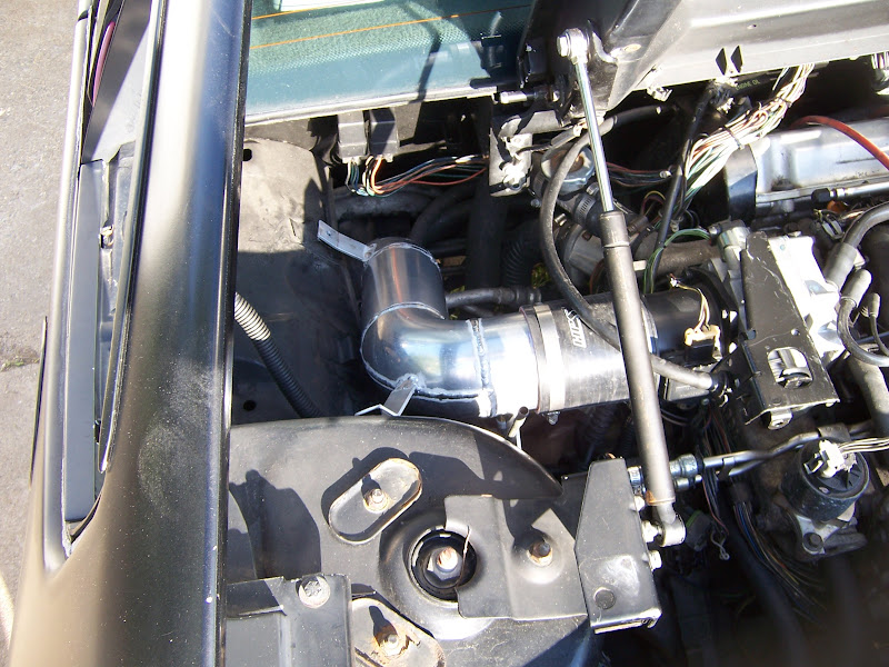
Top view:
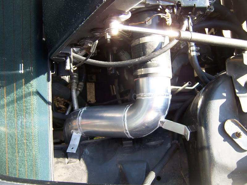
Across the bay angle:

It doesn't show up in any of the photos (I guess that was the idea--to keep it out of sight) but there is a bung for the IAT on the bottom of the tube right next to the coupler to the MAF housing. I re-routed the IAT wires from being bundled with the fuel pump and A/C clutch relays to being bundled with the TPS, IAC and MAF wires.
The CAI can be installed without disconnecting shift cables or removing the shift linkage, but it's very tight and needs a little persuasion in order to squeeze between the bottom edge of the stock fenderwell pass-through and the fuel fill pipe. It's 3.5"... I'm not sure how Sinister got a 4" pipe through.
The induction noise is quite different. The old setup of a mitered stainless pipe with parts store paper filter in the engine bay sounded like a combined jam session with Metallica and Skrillex when I put the loud pedal down and ran out the RPM. Now it sounds more like a sporting V8. I was also surprised to find that I could tell a difference in the location of the source of the sound.
Without further ado, I give you the frankenstien caterpillar pornstar;
With BDSM accessories:
The old crappy setup:
The new hawttness:
Top view:
Across the bay angle:
It doesn't show up in any of the photos (I guess that was the idea--to keep it out of sight) but there is a bung for the IAT on the bottom of the tube right next to the coupler to the MAF housing. I re-routed the IAT wires from being bundled with the fuel pump and A/C clutch relays to being bundled with the TPS, IAC and MAF wires.
-
Shaun41178(2)
- Posts: 8464
- Joined: Fri Nov 19, 2004 7:12 pm
- Location: Ben Phelps is an alleged scammer
Re: The Mule rides again (sort of) - pics.
looks good
FieroPhrek working on that ls4 swap for 18 years and counting now. 18 years!!!!! LOL
530 whp is greater than 312
530 whp is greater than 312
-
Series8217
- 1988 Fiero Track Car
- Posts: 5989
- Joined: Thu Jun 02, 2005 9:47 pm
- Location: Los Angeles, CA
Re: The Mule rides again (sort of) - pics.
Very nice!
Do you have a pressure gauge to see if it performs any better than the old one?
Being that those mounting straps are held on by welded (annealed) aluminum, I suggest mounting them on rubber isolators and maybe adding a gusset to each bracket where it meets the tubing. Despite your silicone coupler, those vibration and slight movement of the engine will cause the welds on those mounting brackets to fail pretty quickly.
-
The Dark Side of Will
- Peer Mediator
- Posts: 15629
- Joined: Wed Nov 24, 2004 11:13 pm
- Location: In the darkness, where fear and knowing are one
- Contact:
Re: The Mule rides again (sort of) - pics.
Tru dat... I'll keep an eye on the tabs.
I can't see that there'd be any difference in pressure. The old one was a 3.25" tube while the new one is 3.5". I expect there will be noticeable reductions in intake temperature. The engine was pulling engine bay air on the dyno and the IAT was showing 100 degrees when it was 60's in the shop, so there's much room for improvement in that area.
I don't know if the corner at the inside of the older miter setup was enough to give problems with flow. I doubt it, considering that the velocity through the tube isn't very high. However, it may have disturbed the flow across the MAF sensor and affected the MAF sensor calibration.
With the tube and knock sensor done, I can go back to the dyno for a touch up any time now. That will be my yardstick for how much better this tube is than the previous. However, the car's running well enough that I don't need to spend $200 on it right away. As I'm still looking for a job, I'll hold off on the re-dyno for a while.
-
The Dark Side of Will
- Peer Mediator
- Posts: 15629
- Joined: Wed Nov 24, 2004 11:13 pm
- Location: In the darkness, where fear and knowing are one
- Contact:
Re: The Mule rides again (sort of) - pics.
1.25" hose elbows on a 1.75" centerline radius: http://www.purosil.com/90mkpolyester.html
These guys have some that have shorter legs so I won't have to trim as much: http://acehose.com/silicone-radiator-hoses.htm
And the same guys from whom I already bought my intake coupler: http://www.hps-siliconehoses.com/hps-32 ... re=default
I should be able to piece together the plumbing for my oil cooler from a bunch of these... just like my exhaust. I'll have more $$ in the plumbing to make it fit under a Northstar Fiero than I'll have in the coolers themselves.
-
The Dark Side of Will
- Peer Mediator
- Posts: 15629
- Joined: Wed Nov 24, 2004 11:13 pm
- Location: In the darkness, where fear and knowing are one
- Contact:
Re: The Mule rides again (sort of) - pics.
I've been thinking for a long time about rear suspension build ideas for the '84-'87 suspension.
An "easy" way to deal with it would be to swap to an '88 cradle. I don't want to go that route for a couple of reasons.
1. I'd have to modify said cradle for the Northstar swap, so custom modification of stock parts is required.
2. Body modification is required in the form of cutting holes for the strut tops. Not a big deal, but still necessary.
3. Unless I build knuckles from scratch or do something kludgey with bearings, I'm limited to the 5x100 wheel bolt pattern and tiny little ball bearings.
4. Being limited to the small hubs also limits me to the Fiero outer CV's, which are a known weakness with high power.
5. While the '88 geometry can accept wider wheels than the '84-'87 geometry, to run the widest wheels the body can handle, I'd still need "strut blocks" to space the struts inward.
However, short of a clean sheet redesign that would eliminate the cradle, I couldn't come up with an "elegant" way of getting an end result that would do what I wanted it to do with minimal fabrication.
I think I just came up with something.
Hear are my requirements/desirements:
1. Correct the '84-'87 rear suspension geometry, consisting of:
1a. Pro-squat
1b. Bump Steer
1c. Low roll center
2. Fit the widest wheels the body can handle. This means pushing the strut as far inward as it will go while maintaining a minimal clearance (1/8" - 1/4") to the lower frame rail.
3. Bolt on large wheel bearings, large outer CV's, bolt on big brakes
4. Bolt on different parts to convert between hub bolt patterns to facilitate wheel and brake hardware improvement
I read somewhere (I wish I could remember where) about a racer being able to bolt Corvette front brakes onto his Olds Alero, which I believe is an N-body. I know from previous research that the N-body and W-body use the same pilot bore and bolt circle to bolt the hub bearing to the knuckle. The W-body uses a pretty large spline where the outer CV drives the hub.
I *think* that the W-body bearing also shares pilot bore and bolt knuckle bolt circle with the C5 Corvette bearing. I will need to have the CarQuest get in one of each so that I can count splines and make measurements to verify.
The Fiero rear suspension is based on the X- and A- body front ends. In those cars, the steering rack was located above the axle centerline, resulting in a relatively high position of the tie rod end boss on the steering knuckle.
The N- and W-body front ends mount the steering rack much lower in the body, below the axle centerline, which means that the tie rod end boss is lower on the steering knuckle.
Because the tie rod boss is lower, I can install a Tie Rod Stud: http://www.speedwaymotors.com/Adjustabl ... ,3333.html and be able to move the toe link down to be in-plane with the control arm, such that the toe link pivots are on-axis with the ball joint at the outer end and the control arm pivot at the inner end, significantly reducing bump steer. However, it will not completely eliminate bump steer as, in the side view, the kingpin axis and control arm pivot axis are not perpendicular.
Also because the Fiero suspension is derived from a front-end, it has pro-squat geometry. This is the result of the rear control arm pivots being *HIGHER* than the foward control arm pivots. This geometry yields anti-squat at a front end, but pro-squat at a rear end. There are two ways to fix this. The first is the way that GM did it with the Indy pace cars: rotate the cradle. This could be accomplished via eccentric forward cradle bushings and wedge spacers are the rear cradle mounts. The second way to accomplish this is to lower the rear control arm pivot. This will reduce pro-squat but will make bump steer WORSE.
An additional hiccup of the '84-'87 rear geometry is that the forward control arm pivots are spaced wider (further from the vehicle centerline) than the rear control arm pivots. I call this "pivot taper". This results in complex relative motion of the strut and control arm, making bump steer virtually impossible to eliminate easily. I suspect that GM did this in order to have a specific affect on caster as the X- or A-body vehicle experienced brake dive.
Both the pro-squat and pivot taper can be fixed by relocating the rear control arm pivot outward and down until pivot taper is eliminated and the control arm pivot axis is perpendicular to the kingpin axis. Having the control arm pivot axis and kingpin axis perpendicular then allows relatively straight forward elimination of bump steer, as outlined above. However, moving this pivot with a stock control arm moves the wheel out of place in the wheel arch.
In summary:
-The most straight forward way to correct the geometry is to move the rear control arm pivot out and down.
-This requires a custom control arm.
-If I build a custom control arm, I'm not limited to the stock, A-body or U-body (minivan) iron knuckles
-Indeed, in order to most readily eliminate bump steer, I should use a later model aluminum knuckle with a lower tie rod end boss.
-If using a later model aluminum knuckle, I have a wider selection of viable combinations of brakes, wheel bearings and outer CV's available.
I deliberately haven't touched on struts and knuckle/strut interface yet, as I haven't ironed that out completely. The strut interface will significantly affect wheel width.
Here's my tenative parts list:
-N-body aluminum knuckles & ball joints
-W-body hub bearings
-W-body outer CV's
-W/F-body 12x1.25" brake rotors
-Y-body (C5 Corvette) front calipers
Control arms will consist of a custom ball joint mount plate and a welded tubular forward leg to a rod-end at the forward control arm pivot. The rod end at the forward control arm pivot can be threaded in and out to provide fine adjustment of the overall track width and the lateral position of the wheel relative to the bodywork.
The ball joint mount plate will include an ear to which a clevis will bolt. The clevis will be connected to a rod end at the rear control arm pivot via threaded adjuster tube. This adjustment will work with the track adjustment at the forward pivot in order to position the wheel fore/aft in the wheel house.
The toe link will share its inner pivot with the control arm rear pivot and its outer pivot will be on a tie rod stud in the N-body knuckle. This will eliminate bump steer by design AND allow a fine adjustment to completely eliminate bump steer that may occur due to body and component manufacturing tolerances.
The rear control arm/toe link inner pivot will be on a bracket which will bolt/and or weld to the stock control arm rear pivot location on the cradle. This bracket will move the pivot out and down relative to stock, as mentioned above.
The W-body outer CV's are, AFAIK, plug/play compatible with the Fiero axle shafts. I @$$ume that they will accept the cages from G6 outer CV joints, facilitating a 6 speed conversion, but I need to verify that.
The W-body hub and W/F-body 12" brakes will fit inside my current 16x8" wheels... just barely.
If the Corvette 5x4.75 hub will interface with the W-body CV's and bolt into the Alero knuckles, I can upgrade to 12.75" C5 front brakes or even 13.5" C6 front brakes when I go to the Vette pattern and WIDE 18" wheels.
This method does not address the roll center or camber curve of the '84-'87 rear. Indeed, lowering the rear control arm pivot will actually make the roll center lower, which is not desired. I don't feel the roll center and camber curve have been demonstrated to be as significant a handicap as the bump steer and pro-squat.
Lots of parts to snag and measurements to take.